|
|
||||||||||||||||||||||||||||||||||||||||||||||||||||||||||||||||||||||||||||||
Trends of the Highway Tunnel Building in Slovakiaby Alojz KopáčikKey words: tunnel building, lay-out, control measurement, 3-D model building Abstract1. IntroductionA multitude of railway tunnels in the Slovak Republic on the one hand and total absence of road-tunnels on the other hand is a paradox which is a result of political and economic development in the post-war period. A comeback to the market economy in the last decenium of 20th century has been connected not only with economic and political changes but also with the decision to eliminate the retardation of traffic infrastructure development. 2. Structure of the traffic network in SlovakiaIn connection with the above fact the necessity has arisen to update the national traffic routes. The Slovak Road Administration has elaborated the "Concept of the Traffic Network Development in the Slovak Republic" which re-evaluates the used network classification as well as the importance of individual routes and their classification under new conditions. The most important traffic routes are included to the network of transeuropean routes, in a volume of 852,8 km. Particular part of the conception are as follows: evaluation of the road network capacity reached, evaluation of traffic safety as well as of ecological conditions and a proposal for the gradual modernisation, including higway construction. Design and construction of highways are in the last years connected to the more demanding parts of the routes D1 and D18. The various geological and morphological conditions of the Karpaty mountains can be not overcome without tunnels. To determination of the number of tunnels and their situation on the highway, are very important the results of the multicriterial evaluation of the region. In connection with this evaluation are designed 17 tunnels, with common longitude of 39 km, on a new highway parts. 3. Driving methods used for tunnel construction in SlovakiaIn present time exist two different groups of methods for the driving of transport tunnels. The first of them is conventional tunnelling on the lines of the principles of the new Austrian tunnelling method (NATM) and the second group is tunnel driving with using tunnel boring machines (TBM). The NATM use for the hard rock excavation conventional mining explosive materials. For the soft rock excavation are used boring machines with cutting head or excavators. Tunnel driving by TBM is more impalpable to the rock and the surrounding of the tunnel is fewer affected. The both of excavation method are know in Slovakia, but the using of TBM for excavation of tunnels with large profiles (highway tunnels) are to this time not used. 4. Management of geodetic works connected to the tunnel constructionThe realisation of large building constructions
need the very "hard" participation of surveyors. The
surveyor participate on the all of tunnel construction phases –
geological investigation and preparation, design and realisation. From
the viewpoint of surveyors is very demanding, if the geological
investigation is realised by prospect drift. In case of the both
largest highway tunnels in Slovakia (tunnel Branisko and Višňové)
are driven the prospect drift. For drift excavation were used both of
the named excavation method (NATM, TBM). The design of tunnel required
ortophotomaps, conventional maps or The basic assumption of successful realisation of the surveying tasks during the tunnel construction, is the existence of a reliable control network. The configuration and type of network are dependent on the required accuracy of measurements, terrain requirements and lay-out methods, which are used. The largest amount of surveying tasks is connected to the tunnel construction. The surveyor groups make "daily service" for the tunnel (lay-out, deformation measurement, measurement of overbreaks, etc.). The divergent accuracy requirements, the necessity of measurements realised in a common system of co-ordinates and their explicit connection to the tunnel construction, results in using of new integrated technology of control measurement. This technology use the modern measurement systems (lasers, electronic theodolites and totalstations) and conventional surveying methods (polygonal method, polar method, free station, etc.). Important part of this conception is the automated storage, transfer and processing of data. To this aim local computer networks on the site, connected by modems, are build. Important part of control measurement is the group of measurement they are oriented to the tunnel surface determination. The aim of this measurements is the determination of the 3-D model of the tunnel surface, which is for volume determination of the overbreaks, of the used materials, etc., used. The model can be the base of the tunnel information system, after their completion by data from another systems (signalisation, cameras, phone, ventilation, etc.) and implementation in a appropriate software. The existence of that system would be the first step to the efficient daily service and the high safety of the future tunnel. 5. ConclusionThe base of the successful realisation of tunnel is the high quality of tunnel lay-out and control measurements. The quality of geodetic works is given by the quality of the control network, the measurement technology used and the professionality of the geodetic personnel. Assoc.Prof. Alojz Kopáčik, PhD 1. INTRODUCTIONA multitude of railway tunnels in the Slovak Republic on the one hand and total absence of road-tunnels on the other hand is a paradox which is a result of political and economic development in the post-war period. A comeback to the market economy in the last decenium of 20th century has been connected not only with economic and political changes but also with the decision to eliminate the retardation of traffic infrastructure development. The maximum elevation of the number of personal car are achieved in years 1985-92, which connection are the traffic intensity over come more then 22% on the highways and first class routes. 2. Structure of the traffic network in SlovakiaIn connection with the above fact the necessity has arisen to analyse of the present time traffic structure and their basis realise the update the national traffic routes. The Slovak Road Administration has elaborated the "Concept of the Traffic Network Development in the Slovak Republic" which re-evaluates the used network classification as well as the importance of individual routes and their classification under new conditions. The new conception was elaborated in the frame of results and
conclusions of the Design and construction of highways are in the last years connected to the more demanding parts of the routes D1 and D18. The various geological and morphological conditions of the Karpaty Mountains can be not overcome without tunnels. To determination of the number of tunnels and their situation on the highway, are very important the results of the multicriterial evaluation of the region. In connection with this evaluation are designed 17 tunnels, with common longitude of 39 km, on a new highway parts (Tab.1). The common budget for the routes they construction are started in years 1997 and later is about 400 mil. EURO. The possibility of Slovakia to finance this project is at the present time given by 15-20 mil. EURO per year (Mikolaj, 1998). For the acquisition of missing finances were new sources searched. In the frame of the projects PHARE and TINA were international finances (about 100 mil. EURO) acquiesced for the period 1998-1999. To finish these projects is the primary goal of the period 2000-2005. Table 1
3. Driving methods used for tunnel construction in SlovakiaEach tunnelling method can be understand as time and space harmonised technology of tunnel cutting and construction of primary cheek of the tunnel, which support the rock stability. At the present time exist two different groups of methods for the driving of transport tunnels. The first of them is conventional tunnelling on the lines of the principles of the new Austrian tunnelling method (NATM) and the second group is tunnel excavation with using tunnel boring machines (TBM). The NATM use for the hard rock cutting conventional mining explosive materials. For the soft rock cutting are used boring machines with cutting head or excavators. The NATM as well as another tunnelling methods will maximum to active the rock for the supporting of the future tube. This can be attained in interactivity of the tunnel primary cheek and the knowledge of rock deformations. The NATM prefer the technology of shared cutting – calote, middle part and sole (Fig.1). Each of these sequences can be once more shared. The profile can be given by arcs with continuous curvature. The primary cheek is build by sprayed concrete, steel grating and steel arc’s which are completed with rock anchors. To dimensioning of the primary cheek will be given not only by the thickness of the sprayed concrete especially by using of different number and type of the anchors. The right dimensioning of the primary cheek is controlled by group of geotechnic and geodetic measurements. 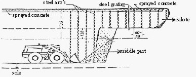
Fig 1. Shared tunnel profile by using of the NATM Using the full profile excavation accelerates the tunnel construction. From the viewpoint of geodetic measurements demanding this procedure higher accuracy of excavation. The geodetic measurements that are needed by using of TBM are different from the measurements realised by the NATM. From the operating personal of the TBM is required the continuous control of the position and orientation of the TBM. The higher accuracy of lay-out is required especially in cases if the tunnel is driven without prospect drift. Geodetic measurement realised by tunnel excavation with TBM is:
Tunnel driving by TBM is more impalpable to the rock and the surrounding of the tube is fewer affected. The both of driving methods are know in Slovakia, but the using of TBM for excavation of tunnels with large profiles (highway tunnels) are to this time not used. TBM are used for driving of prospect drifts only (Frankovský, Kapusta, 1998). 4. management of geodetic works connected to the tunnel constructionThe construction of large tunnels needs the very active participation of surveyors. The surveyor participates on the all of tunnel construction phases – geological investigation and preparation, design and realisation. The volume of geodetic works is generally appropriate to the function, size and structure of the object. The construction of the structural object required:
In the case of tunnel constructions a great amount of design of the local network, the lay-out and control measurements, especially with regard to the required accuracy characteristics, they by technical norm STN 73 0422, must be given. The design of tunnel required ortophotomaps, conventional
maps or 4.1 Tunnel control networkThe basic assumption of successful realisation of the surveying tasks during the tunnel construction, is the existence of a reliable control network. The configuration and type of network are dependent on the required accuracy of measurements, terrain requirements and lay-out methods, which are used. The extraordinarily of these networks accentuates that their parts are situated separately and build sequentially by heterogeneous geometric forms. The tunnel network is shared once more to part on the surface and underground. The underground part of a tunnel network is build sequentially from the portals by two polygons. The network part on the surface is build before the start of the tunnel construction. This part consists of triangles and quadrangles, usually formed around portals and ventilation shafts. The parts of the tunnel network on the surface are very distant from one another and separated by many terrain obstacles. The connection of these parts to one homogenous network can be solved very effectively using the satellite system NAVSTAR GPS (Navigations Timing and Ranging - Global Positioning System). The use of GPS enables the connection of the network parts, without direct visibility among points. The network configuration must assure the appropriate conditions for the GPS observation (visibility of the observed satellites, appropriate elevation angle, etc.). All control points cannot be positioned optimally for the GPS measurement. The parameters of these points must be improved by terrestrial measurements (distance and angle measurements). The application of GPS gives higher accuracy to extensive networks used for construction of tunnels with length of more than 5 km. The present-day technologies of geodetic measurement (electronic theodolites and total stations, GPS) enable us to obtain the network accuracy higher than the accuracy of the land network (the required values are given by sx, y=5-7 mm). The control networks of tunnels are therefore built as local networks. The connection of these networks to the land network has only a secondary significance and is realised especially for design structural objects of the tunnel. The definition of the control network as a local network required the design of the tunnel in the local co-ordinate system. The transformation from WGS-84 to the local system is given by six parameters (3 rotation and 3 translation parameters, without scale factor). It is very important to define the limits of relevance of the local network and the co-ordinate system. The objects situated outside this area will be designed in the land co-ordinate system. The highs of control points are determined by precise nivellement with connection to the land nivellement network. Closed nivellement polygons determined by two independent measurements are usually used. The required accuracy of high points are given by sH=1-2 mm. The points are positioned in the surroundings of the tunnel portals and ventilation shafts. The control network is the basis of all geodetic measurements realised before, during and after the tunnel construction. Therefore points require special stabilisation and protection. The so-called deep stabilisation is used, realised borehole completed by concrete (Fig.2). The heads of these points are equipped with universal compound, used for forced centration of instruments, marks, prismas and GPS receivers.
4.2 Geodetic measurements during the tunnel constructionGeodetic measurement during the tunnel construction can be shared in the measurements and lay-out realised on the surface and measurements and lay-out realised in underground. Both groups of these measurements are suitably connected to each other and build indivisible part of tunnel construction. Before the start of geodetic measurements it is necessary to consider which methods are chosen for the measurements realised on the surface and underground, how many times the realisation of geodetic works is necessary and what is the accuracy required for these measurements. The underground constructional works can be shared in three technological phases:
These operating procedures must be respected by lay-out realised in underground. For the measurement and lay-out realised by tunnel driving are used the tunnel surveying systems (CATS from Angermeier Ingenieure, GTS from Geotronics, ITMS from Leica, e.t.a.). In addition to the know systems, are used self-programmed systems in Slovakia. For the lay-out of the tunnel axis the polygons are usually
used. For the building of longer tunnels two polygons are used - the basic and
the auxiliary or working polygon. At present time is the method of free station
used, which enables the more efficient measurement and lay-out. The points of
the basic polygon are regularly controlled (monthly, quarterly). Each of the
control measurements includes the observations of all polygon points, including
the connection of the tunnel control network on the surface part. The results of
the control measurements are the new co-ordinates of these points, compared to
the source values. Using error analysis and statistical tests can be decided, if
the difference between the source and the new values is statistically
significant. In the case of proved significance of these differences the new
co-ordinates are accepted. It is very important to take care of the uniform and
precise actualisation of the list of 4.3 Control measurementsThe tunnel construction effects the environment and causes the settling of the surface layers. The cause can be the rocking of subsurface layers or the tunnel construction. The beginning of the transportation can affect the position of the tunnel and the constructions on the surface. These changes will be consecutively stabilised, but can indicate in certain phase the risk requiring the necessary arrangements. The control measurements are planned already within the tunnel design. Realisation of these measurements enables the registration of assumed translations of the tunnel, the tunnel over layers and the buildings on the surface. The aim of geodetic control measurements is the determination of deformations of the tunnel, the surface and the buildings over the tunnel. By these measurements the horizontal and vertical deformations of these objects are determined. The accuracy of control measurements is determined by design of the tunnel or by norm STN 73 0405. The development of tunnel constructions in the last years lay higher claims to the measurements. Besides the higher accuracy the relation of all measurements to the control network is required. A discharge of this requirement would be possible only with the connection of geotechnical and geodetic measurements by the common system of 3-D co-ordinates. These measurements are realised by the group of control points situated at each cross profile, symmetrically to the vertical tunnel axis (Fig.3). There are situated 3 or 5 points in the calotte, 2 points in the sole. The distance of two cross profiles is given by geological conditions of the rock and generally is chosen by 25 m. In the wrong surroundings can be this given by 5 to 10 m.
The number of realised control measurements has a downward tendency. One or two measurements are realised in a first day, afterwards two or three measurements in a week. The measurements are realised to the time, whom the points can be seen as stabilised. The profile will be active after opening the sole and new control measurements must be realised. The divergent accuracy requirements, the necessity of measurements realized in a common system of coordinates and their explicit connection to the tunnel construction, results in using of new integrated technology of the control measurements. This new technology uses the modern geodetic measurement systems (lasers, electronic theodolites and total stations) and classical geodetic methods (polygonal method, polar method, free stations, etc.). The indivisible part of this conception is the automated storage, transfer and processing of data. To this aim local computer networks on the site, connected by modems, are builds. It is advantageous the using of the central server, that enables the simultaneous access of data for all users. The necessary hardware gives not specific requirements at the future users. The use of computers with rapid high-resolution video cards is advanced. The computers used in the surroundings of the direct building activity must be protected against the dust, humidity and vibrations. It would be the industry computers or different notebooks used. The used software enables the immediate data processing and design of necessary documentation:
The measurements for the determination of volume of the over breaks are introduced to the group of control measurements realised by geodetic methods. The basic assumption of the volume determination is the measurement of the soffit in the tube. That is very important determinate, which of over breaks are geologically required and which are effected using the wrong driving technology. The over breaks are filled by concrete, because volume of over breaks effects the divergence of secondary costs. The control and determination of quality and safety of tunnel construction need the measurement of thickness of the concrete, too. Both of these measurements' results to the determination of the volume of used materials (concrete). The number of profiles used for convergence measurements and deformation determination is too small for the volume determination. The using of more profiles is also expensive. With this aim are search methods, these use the natural mark of measured points only. There are two ways for solution of this problem; the photogrammetric method and the using of laser distance meters. The disadvantage of the classical photogrammetric method is the between the measurement and requirement of results needed time (can be one or two days too). This time is needed for the processing of analogue pictures and their photogrammetric interpretation. This disadvantage fully eliminates the real-time photogrammetric systems working on the base of CCD cameras. The pictures are disposed in the digital form and instantaneous. With regard to the high price of the real-time photogrammetric systems, the combined analytical systems are more used. The pictures are executed by analogue cameras (metric or non-metric cameras) and after the scanning are processed by analytical softwares. This method enables to attain the high accuracy and performance. With coming of efficient laser distance meters, there measure without prismas, the polar method for the volume determination and profile measurement can be used. The systems based on the laser distance meters are more advantage as well as arbitrary photogrammetric system. When these systems are equipped with appropriate software, the results can be attained immediately in the field. The disadvantage of these systems is that the major part of the work must be realised under demanding conditions of the direct building activity. 5. ConclusionThe base of the successful realisation of tunnel is the high quality of tunnel lay-out and control measurements. The quality of geodetic works is given by the quality of the control network, the measurement technology used and the professionally of the geodetic personnel. The divergent accuracy requirements, the necessity of measurements realised in a common system of co-ordinates and their explicit connection to the tunnel construction results in using of new integrated technology of control measurement. Important part of this conception is the automated storage, transfer and processing of data. To this aim local computer networks on the site, connected by modems, are builds. Important part of control measurement is the group of measurement they are oriented to the tunnel surface determination. The aim of these measurements is the determination of the 3-D model of the tunnel surface, which is for volume determination of the over breaks, of the used materials, etc., used. The model can be the base of the tunnel information system, after their completion by data from another systems (signalisation, cameras, phone, ventilation, etc.) and implementation in an appropriate software. The existence of that system would be the first step to the efficient daily service and the high safety of the future tunnel. ReferencesMikolaj, J., 1998: Concept of the Road Network Development in the Slovak Republic. 60th Anniversary of the Faculty of Civil Engineering of the STU Bratislava, p.407-413, Bratislava, Faculty of Civil Engineering of the STU. Frankovský, J., Kapusta, J., 1998: The Renaissance of Tunnel Construction in Slovak Republic in late 20th Century. 60th Anniversary of the Faculty of Civil Engineering of the STU Bratislava, p.235-240, Bratislava, Faculty of Civil Engineering of the STU. Since 1998 Associate Professor at the Slovak University of Technology in Bratislava. Study of Geodesy and Cartography at the University in Bratislava, doctorate degree (PhD.) 1986, 1987-1998 Senior Lecturer at the Department of Surveying of the Slovak University of Technology in Bratislava. Guest lecturer and research worker at the University of Technology Budapest (Hungary), University of Technology Vienna (Austria) and the Slovak Academy of Sciences in Bratislava. Lectures at the Technical University of Dresden (Germany), Technical University of Novosibirsk (Russia), University of Technology Vienna (Austria), University of Miskolc (Hungary) and Research Institute of the Hungarian Academy of Sciences Sopron (Hungary). Member of FIG Working Group 6E, Special Commission 4 of IAG and the Proof Commission of the Slovak Board of Surveyors and Cartographers, TC 89 Geodesy for STN in Slovakia 1999. Author of about 50 publications, 2 books, and 22 conference presentations. Assoc. Prof. Alojz Kopáčik, PhD Faculty of Civil Engineering Slovak University of Technology E-mail: kopacik@svf.stuba.sk 27 March 2000 |
||||||||||||||||||||||||||||||||||||||||||||||||||||||||||||||||||||||||||||||
|
|