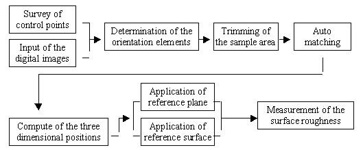
OBJECT'S SURFACE ROUGHNESS MEASUREMENT USING A HIGH RESOLUTION DIGITAL CAMERAHyosung LEE, Yangdam EO, Yongil KIM and Kiwon AHN, KoreaKey words: AbstractThis study aims to present an extraction of the three-dimensional positions and precision measurements of an Object's surface roughness using stereo digital image data obtained from a high resolution DCS 420 digital camera. For real-time processing, a primary window operating roughness measurement system was constructed by means of Visual basic 6.0 in Windows. This system is composed of six modules; image edit, control point survey, bundle adjustment, automatic matching, three dimensional positions generation, and roughness measurement. As the analysis results of measurement accuracy for a digital camera that uses this system, the roughness error of the normal distance between the best fitting reference surface obtained by the least square method and sample points in the ideal plane or surface did not exceed ±0.1mm 1. INTRODUCTIONIndustrial products or instrumental components and structures of various manufacturing methods do not correspond indispensably to a design plan. Also, because surface roughness for quality control is a very important physical quantity and closely associated with the character of the material, it should be measured in the sub-millimeter order. Especially, the manufactured stone is used in the construction materials sectors, also, because the roughness of manufactured stone is very small, a precision measurement method must be used to obtain accurate values. Since most of the methods for surface roughness precision measurement measure very small segments of metal or assembly machines in the laboratory, structures of forms such as the manufactured stone are unsuitable for measurement. So, the digital close-range photogrammetric technique which can be measured directly on the field site is considered to be an efficient method. In addition to this technique should be measured as accurately as possible to the extent of sub-millimeter order, if using a high resolution digital camera which can directly download to a notebook computer in the field, can quicken the process and make it more effective. This paper aims to construct a stone's roughness measurement system using a digital camera and Microsoft Visual basic 6.0 of Window environment for real-time measurement. Also, after acquiring digital images of the ideal plane and surface stone are scarcely roughness using the DCS 420 digital camera, surface roughness was measured using the reference surface that was computed by the least square method, and the measured result values were compared with the result values by the Rolleiflex 6006 metric camera for evaluating the processing capability of the surface roughness measurement of the DCS 420 digital camera. 2. CONSTRUCTION OF A PRIMARY INTEGRATED ENVIRONMENTIf subjects that utilize surface roughness measurement by the digital close-range photogrammetric technique are constructed independently from the integrated environment, this can quicken the process and make it more effective. Thus in this paper, a primary roughness measurement system is constructed that uses a digital camera and Microsoft Visual basic 6.0 of Window environment for real-time processing. A menu module on this system was constructed as sub-menus that image viewer, survey of control points, geometric correction, bundle adjustment, auto matching, computation of three-dimensional positions, and surface roughness, after the main screen menu was constructed using a Multiple Document Interface form for convenient use. In the case where a sub-menu consists in the main screen menu, the main screen menu provides workspace in the application program for the sub-menu screen. Figures 1 and 2 show the flow chart and main screen menu of the constructed system.
Fig. 1. Flow chart of the roughness measurement system.
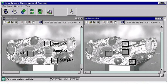
Fig. 2. Roughness measurement system. 3. SURFACE ROUGHNESS MEASUREMENT OF THE SAMPLE AREAS3.1 Acquisition of The Digital ImagesThe test objects used a reference stone (width: 75cm, height: 30cm, depth: 30cm) which has the ideal plane or surface for measurement accuracy appraisal. Asterisk-shaped targets (diameter of the central circle is 1.0mm) were glued onto each stone, and the targets have 15 control points and 10 check points for photogrammetry. Photographs were taken using the Kodak DCS 420 digital camera which, with its high resolution CCD(Charge Coupled Device) sensor(1524×1012 pixels of 9×9 size), provides 340MByte memory on an internal hard disk for 203 frames. The digital images acquired by a CCD chip (width 13.8×height 9.2mm) can be transferred into a PC via an SCSI interface. Stereo images of the objects were obtained by converging photographing of the left and right camera lenses. The lenses were used with 35mm focal length (photographing base: 1.2m, photographing distance: 2.0m) and 70mm focal length (photographing base: 2.0m, photographing distance: 4.0m). The positions of a camera and targets were measured by the triangulation principle using the two Wild T2 theodolites. The sample area for evaluating processing capability for surface roughness measurement of the DCS 420 digital camera was objectified for the ideal surface area(sample 1, 2) and the plane area (sample 3, 4) as shown in Figure. 3.
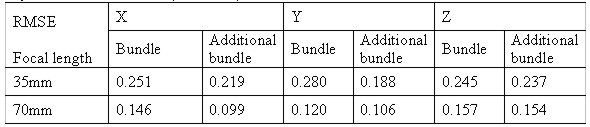
Fig. 3. Edit module of image viewer. 3.2 Determination of The Exterior Orientation ElementsThe bundle adjustment is applied to results of the exterior orientation elements from each camera. The bundle adjustment is based on the collinear condition, which refers to the perspective center of a camera, the points on the photograph, and the points in the object space being aligned in the bundle of rays. Rotation elements( , , ) and the perspective center position of camera at the moment of exposure(X0, Y0, Z0) resulted from the least square method. In this paper, the exterior orientation elements of digital images acquired by the DCS 420 camera are not calibration data, so the interior and the exterior orientation elements were resulted from the bundle adjustment using the additional parameters of principal displacement and focal length. For reliability evaluation of resulting exterior orientation elements, space coordinates of check points in each object space are computed by the bundle adjustment. The accuracy of the computed positions is evaluated from RMSE of residual errors between positions measured by the T2 theodolite and computed positions by the bundle adjustment, and Table 1 presents the results. Table 1. RMSE of 3D ground coordinates of the check points in digital images acquired by the DCS 420 camera (unit : mm)
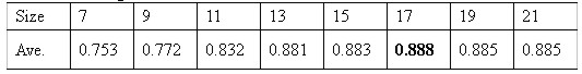
As shown in Table 1, RMSE of images with 70mm focal length is less than the case of 35mm, and the additional bundle adjustment gives higher accuracy than the bundle adjustment. So, in this case, we just used digital images of the reference stone acquired by the 70mm focal length digital camera. 3.3 Auto MatchingAuto matching for the acquisition of object space coordinates is commonly used in area-based matching method using the maximum correlation coefficient, which is computed based on the cross-correlation function, and this method was used in this paper. Also, pre-processing of auto matching where the matching size should be determined. Thus, in the determination of matching size, after conjugate points determined to have 20 pixel intervals using geometrical relation equation in the targets of between left and right images, the determined conjugate points are used as control points for matching. Search size fixed as 45×45 in the control points surrounding, and averages of the maximum correlation coefficient of each window size from 7×7 to 21×21 are calculated by matching, so that 17×17 window and 45×45 search are the proper sizes for matching as shown in Table 2. Table 2. Average correlation coefficients of each window size
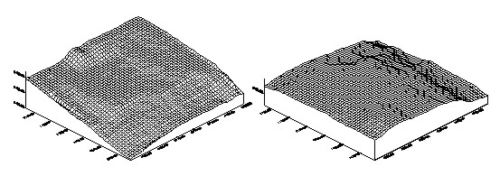
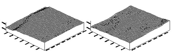
After all the points of each sample area were matched using the resulted matching size, we obtained conjugate points of the sub-pixel unit. 3.4 Determination of The Three Dimensional PositionsObject coordinates were generated by applying the space intersection theory, where conjugate points are resulted by matching, and exterior orientation elements are obtained by the calibration process of systemic error. Figure 4 shows the DEM of each sample area.
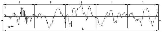
Fig. 4. DEM on each sample area taken by the DCS 420 camera. 3.5 Surface Roughness MeasurementOne of the representation methods of surface roughness currently provided in the KS is the centerline average roughness, which is mostly used as international measures. As can be seen in Figure 5 and Equation 1, this method uses the absolute value of the arithmetic mean of height differences from the reference surface, that is, the minimum surface of height value differences at all points of the test area.
Fig. 5. Profile of a curved line for the centerline average height roughness designation method.
The reference surface that has minimum-distance values between the heights of all points in the sample area was determined by the least square method. Then, distances from the reference surface to all points were computed as centerline average roughness in this paper. The plane equation for the determination of the reference plane is defined as shown in Equation 2. The coefficient of this equation is computed by the least square method from Equation 3 of function F, and the normal distance from an arbitrary point in the sample area to the reference plane should be computed in accordance with Equation 4.
Where Xi, Yi and Zi are positions of arbitrary points in the object space. Also, a two order surface equation is defined in Equation 5 for the determination of roughness from the reference surface, and the coefficient of this equation is computed by the least square method just as in the plane equation. And the normal distance from an arbitrary point in the sample area to the reference surface should be computed by a unit normal vector as shown in Equation 6.
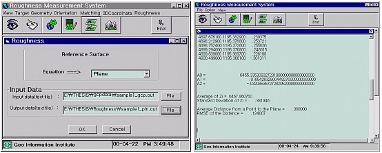
Surface roughness from the reference plane and the reference surface to all points in the sample area were computed with the proposed method in this paper. Figure 6 presents the module of surface roughness measurement and output values, and Table 4 presents centerline average roughness from applicative reference plane and surface to all points in the sample area.
Fig. 6. Roughness measurement module. 4. COMPARISON AND ANALYSISIn order to evaluate measurement processing capability of the DCS 420 digital camera, resultant values of a digital camera were compared with the resultant values of surface roughness obtained by using the Rolleiflex 6006 metric film camera. Sample areas of digital images acquired by the Rolleiflex 6006 metric camera evaluated the same areas as did digital camera. Also, the three-dimensional position of each sample area was computed by applying the space intersection theory, where conjugate points resulting from matching are used for all pixels in the sample area images. Surface roughness is computed with application of mentioned reference plane and reference surface equation using the resulting three-dimensional positions information, as shown in Table 3. Table 3. Average of normal distance between the sample points and the reference surface from the DCS 420 digital camera and the Rolleiflex 6006 camera(unit : mm)
The average of surface roughness from the DCS 420 digital camera shows inaccurate results with approximately 0.03mm greater values than those of Rolleiflex 6006 metric camera as a whole, as shown in Table 4. The reason for this result is that a digital camera is a nonmetric camera without calibration data and resolution by the CCD sensor is fixed as 1524×1012 pixel, and pixel space of CCD arrangement is not constant. On the other hand, metric camera provides calibration data related with lens distortion, and the resolution of metric camera can be adjusted at user's disposal after film scanning. 5. CONCLUSIONFrom stone's surface roughness measurement using stereopairs of the ideal plane or surface acquired by DCS 420 digital camera and a primary window operating roughness measurement system,
Results of this study may be applied to industrial measurement of high precision demanded by the digital close-range photogrammetric. REFERENCES
CONTACTHyosung Lee Yangdam Eo Assoc. Prof. Yongil Kim Professor Kiwon Ahn 13 April 2001 This page is maintained by the FIG Office. Last revised on 15-03-16. |
||||||||||||||||||||||||||||||||||||||

 (4)
(4) (6)
(6)