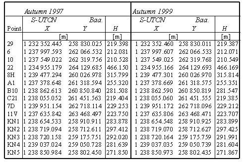
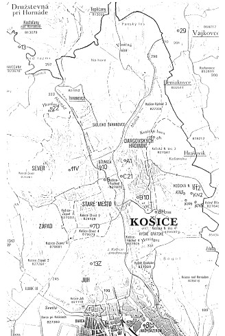
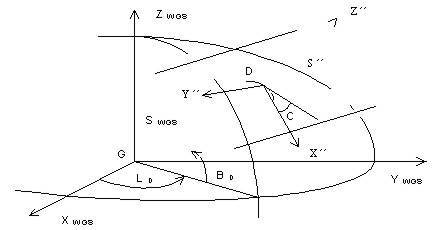
GPS MEASUREMENTS OF THE GEOTECTONIC RECENT MOVEMENTS IN EAST SLOVAKIAProf. Vladimir SEDLAK, SlovakiaKey words: GPS, 3D transformations, topocentric coordinate system, free adjustment, adjustment with constraints, deformation teststatistics. AbstractThe paper deals with transformation procedures observed GPS (Global Positioning System) data from the World Geodetic System WGS-84 into the national geodetic grid datum S-UTCN (System of United Trigonometric Cadaster Network) and Baa.(The Baltic Sea after adjustment). GPS measurements are situated into the geodetic network in the Košice-Valley for a purpose of deformation surveying geotectonic recent movements in the East-Slovak regions. Adjustment with constraints and free adjustment are applied at determining coordinates of the geodetic network points. Transformation from WGS-84 into S-UTCN is the most frequently by means of using the 7-element Helmert transformation with using three identical points. Geodetic network was adjusted by two ways. In a case when datum parameters are absolutely accuracy then an adjustment with constraints is considered; in a case when datum parameters are determined with a concrete accuracy, what has also an influence on an accuracy of adjusted parameters except on measured accuracy, then a free adjustment is considered. The GPS measurements are realised on points of the geodetic network (GN) localised in the Kosice-Valley (Slovakia). The aim of these measurements is determining recent geotectonic movements in the urban agglomeration of Kosice-city. 3D coordinates of the network points determined from satellite navigation present a realisation result of the solved scientific project at the Department of Geodesy and Geophysics of the Technical University of Kosice since 1997. GPS measurements are periodically realised twice a year (spring and autumn). Altogether, 17 points of GN are measured by means of using the GPS static method. A priority of the chosen static method for our measurements is above all a high accuracy in determining point position, which is conditioned by longer period of measurement on a determined point (cca 45 minutes). The determined GN points are solved by double GPS vector technology always regarding two reference points, i.e. three GPS receivers are used for measurements. These points are placed so that the territories in which some geotectonic movements are presupposed according to geologists. The main tectonic fault in the Kosice-Valley, according to which two expressive geological faults of the Earth ground blocks should move, is assumed in the north-south direction along the river Hornad. The secondary tectonic faults of smaller extent are in the direction perpendicular to the Hornad fault, i.e. in the east-west direction. These secondary tectonic faults are mutually parallel. Three double-frequency GPS receivers Sokkia GRS 2100 were used to measurement. Adjustment of observed data was realised by the firm software Prism ver 2.1 Sokkia. Coordinates of all points in GN were transformed from WGS-84 into a plane coordinate system S-UTCN, which is obligatory coordinate system for realisation of geodetic works in Slovakia. The non-linear rotary matrix method was applied to the adjustment. After transformation, the coordinates were consecutively adjusted by an adjustment with constraints. For a purpose of deformation consideration in the monitoring network the coordinate differences are subjected to the teststatistic hypotheses. A size of deformations is presented by the deformation vectors on the individual network points. Modelling deformations in the Kosice-Valley is based on GIS data by means of using the MicroSoft and Kokes software. IntroductionThe GPS measurements are realised on points of the geodetic network (GN) localised in the Kosice-Valley (Slovakia) (Fig. 1). The aim of these measurements is determining recent geotectonic movements in the urban agglomeration of Kosice-city (Sedlak et al., 1998). 3D coordinates of the network points determined from satellite navigation present a realisation result of the solved scientific project at the Department of Geodesy and Geophysics of the Technical University of Kosice since 1997. GPS measurements in the KoSice-ValleyGPS measurements are periodically realised twice a year (spring and autumn). Altogether, 17 points of GN are measured by means of using the GPS kinematic method. Priority of the chosen kinematic method for our measurements is above all a high accuracy in determining point positions which is conditioned by the period of measurement on a determined point (cca 5 minutes). The accuracy of the kinematic methods is same like at the static method (Hofmann-Wellenholf et al., 1993; Seeber, 1993; Leick 1995). The determined GN points are solved by double GPS vector technology always regarding two reference points, i.e. three GPS receivers are used for measurements. These points are placed so that the territories in which some geotectonic movements are presupposed according to geologists. The main tectonic fault in the Kosice-Valley, according to which two expressive geological faults of the Earth ground blocks should move, is assumed in the north-south direction along the river Hornad. The secondary tectonic faults of smaller extent are in the direction perpendicular to the Hornad fault, i.e. in the east-west direction. These secondary tectonic faults are mutually parallel (Jacko, 1997). Figure1. Positioning the Kosice-Valley GN (1:100 000). Three double-frequency GPS receivers Sokkia GRS 2100 were used to measurement. Adjustment of observed data was realised by the firm software Prism ver 2.1 Sokkia. Coordinates of all points in GN were transformed from WGS-84 into a plane coordinate system S-UTCN, which is obligatory coordinate system for realisation of geodetic works in Slovakia. The non-linear rotary matrix method was applied to the adjustment (Melicher and Flassik, 1998). After transformation, the coordinates were consecutively adjusted by an adjustment with constraints. COORDINATE TRANSFORMATION OF THE GN POINTS FROM WGS-84 INTO S-UTCNSystem NAVSTAR GPS uses WGS-84 with the purpose of expressing the position anywhere in the earth and space. The reality that the GPS system determines a position in global dimensions is its priority. However, the disadvantage for surveying is its limitation in a plane rectangular system that is our national geodetic grid S-UTCN (system S). Transformation of coordinates from WGS-84 into a topocentric horizontal systemThe coordinate axes (X, Y, Z)WGS-84 with an origin in the centre of ellipsoid create the system SWGS-84 (Fig. 2). The coordinate axes X´´, Y´´, Z´´ create the topocentric horizontal coordinate system S´´ (Melicher and Flasik, 1998; Hurcikova, 1998). Its origin lies in the point D. Point D is one point belonging to points of a local network. This point is situated approximately in its centre. To assume that the geodetic horizon in D is a parallel plane to S-UTCN is only possible in a case of local GN with a small dimension (if distances between network points are not longer than some units of kilometres). Table 1 presents coordinates of the point D. Axes X´´ and Y´´, which lie in a geodetic horizon of the point D, while the axis X´´ is oriented into the south branch of a meridian. The axis +Z´´ lies in a normal line and is directed into the geodetic zenith and the axis +Y´´ creates with the mentioned axes a left-hand system.
Figure 2. SWGS-84 and S´´. Table 1. Coordinates of the point D in WGS-84 and S-UTCN.
Transformation of coordinates from the system SWGS-84 into the system S´´ is a possible according to the following equation
where index D means that the tangent point is considered, D,(D) is ellipsoidal geocentric latitude, (longitude) of point D, RY (90° - D ), RZ(D ) are non-linear rotation matrices according to the following equations (Melicher et al., 1993)
The coordinates of the GN points in WGS-84 are obtained by a convenient adjustment of measurements, which were realised by the system NAVSTAR GPS. The right-hand system is changed into left-hand which is preferred in geodesy. This change can be reached by multiplying a diagonal matrix with the diagonal (1, -1, 1). The point D has the coordinates (X, Y, Z)T=(0, 0, 0)T in the system S´´. The system S´´ is also possible to obtain by using the following equation
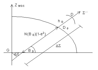
where D X is distance of the normal from the centre of the ellipsoid, D Z is a displacement of the plane XY into the point D in the normal direction. In the sense of Figure 3, the quantities D X and D Z are derived according the equations
where A(D) is the transverse radius of curvature in the point D, e is the numerical eccentricity, HD is the ellipsoid height of the point D. A transition between the local and the commonly used national system should be the simplest in their contact point for a purpose of using the state network. It means that the coordinates of the local network should not much differ from S-UTCN. It can be reached by turning the system S´´ in the point D about the meridian convergence C (Fig. 2) of S-UTCN and by displacement of the origin of the system S´´ round the rectangular coordinates XD, YD in S-UTCN. The mentioned transformation is expressed by the following equation
where RZ(-C) is the rotation matrix determined by the equation
and hD is the over-sea level height of the point D in the Baltic sea elevation system after adjustment (Baa.). In this way we obtained the topocentric horizontal coordinate system whose the coordinate axes X´, Y´ lie in the geocentric horizon of the point of normal intersection of the point D with the geoid. Because the point D has the coordinates (0,0,0)T in the system S´´, then this point will obtain identical coordinates with the coordinates in S-UTCN by adding the vector (xD,yD,hD)TS-UTCN .
Figure 3. Transformation from the geocentric into the topocentric system. Transformation of coordinates into the local coordinate systemIt is not possible to calculate directly the values of elements which would harmonise with the values measured in a terrain using the coordinates of points in the system S´. These coordinates are influenced by the Earth curvature and also by a relative difference in elevation of point over the horizon plane. Regarding to a network dimension, we can substitute the ellipsoid by the reference sphere whose radius is equal to the mean radius of the Earth curvature R in the point D according to the equation
where M is the meridian and N the transversal radius of curvature of the ellipsoid, which are described by the following equations (Mervart and Cimbalnik, 1997)
where a and e2 are the constants of the used ellipsoid (the semimajor axis and square of the 1st numerical eccentricity) (the Bessel ellipsoid). An influence of the difference of elevation is possible to eliminate if the coordinates X´, Y´ are reduced into the intersection of the normal with the tangent plane, or with the basic plane. The reduction from a relative difference of elevation is possible to influence significantly by moving the geodetic horizon into the basic plane of GN in the height z0. This height equals to approximate mean elevation value in which geodetic measurements are realised. The reduction of the coordinates X´, Y´ of the GN points in the system S´ into the intersection of the normal with the basic plane equals to a gnomic projection which regarding to the network dimension is considered a conform projection. The presented method has several priorities. Above all, it is the fact that a high relative accuracy in determining point positions by means of using NAVSTAR GPS technology is not lost. Similarly a measurement on one identical point is only enough instead of three identical points, by that a transmission of some errors at the transformation can be reduced. Reductions from elevation and cartographic distortion are needed in S-UTCN where only reduction from a relative height or elevation is considered in some local system. This reduction is also minimised by a convenient choice of transformation parameters (Melicher and Flassik, 1998). Adjustment with constraints of 2D geodetic networkGeodetic networks can be adjusted by two ways. If we consider datum parameters as absolutely accurate and we do not include them into an adjustment process, the adjustment with constraints is considered in this case. In fact that datum parameters are also determined with a concrete accuracy that has an influence on an accuracy of adjustment parameters except for measurement accuracy. In this case a network can be adjusted by a free adjustment with consideration of datum parameters (Mervart, 1994). Regarding the applied confinement adjustment in the Kosice-Valley GN a theoretic procedure of this adjustment is presented, which is the most convenient for our national geodetic grid S-UTCN. The least mean square method (LMSM) is chosen as an estimate principle, and the inverse solution is chosen as a mathematical principle, which is a standard procedure in an adjustment of GN. After adjustment the position and form of GN are changed but the datum point positions are not changed (datum points are considered as absolutely accurate). This fact is presented so that the configuration matrix A and also the matrix N of GN will be regular; the rank of matrices h(A)=k, h(N)=k, where k is a number of determined parameters. For the adjustment the following four vectors and matrices are necessary to be:
It is the matrix in which cofactors of the measured quantities are occurred. These cofactors can be calculated according to the equation
where
Solving equations of the estimate statistic model by means of using MSM we will get the following the linear equation AT. where dl=l-lo is the vector of reduced observations, while l is the vector of the observed quantities and lo is the vector of the approximate values of the measured quantities. If we indicate N=AT.
After adding
The quality of the adjusted network is universally characterised by two matrices: - the cofactor matrix of the estimatesof coordinates
of coordinates
where
in which a numerator expresses the quadratic form of corrections W and a denominator expresses the number of superfluous measurements (redundantion of a network). A presumption of better quality of GN will increase together with increasing the difference n-k. The vector of corrections v is determined by the equation v=A. Table 2. The adjusted coordinates of the GN points in S-UTCN.
The covariance estimates of the coordinates are
situated on a diagonal of the covariance matrix in a direction of
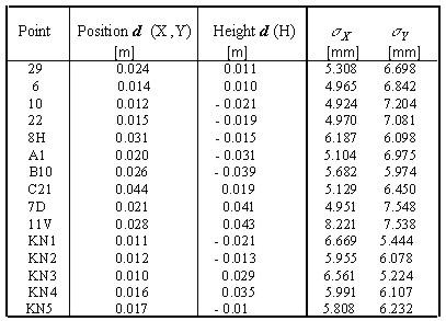
individual axes. The adjusted values of the measured terms Deformation vector d was estimated by a simple way, i.e. algebraic calculations in rectangular triangles in the plane of S-UTCN. Position deformation vector presents deformations in a plane of X,Y axes and height deformation vector presents deformations (subsidences) in the Baltic sea level system as a difference between the heights on the GN points. Table 3 presents the deformation vectors with standard deviations of the GN points. Because all deformation vectors are in limits of the error circles, we did not presuppose any recent geotectonic movements in the Kosice-Valley. Table 3. The deformation vector d (in position and height) and standard deviations of the GN points.
CONCLUSIONSThe results of measurements by GPS technology confirm a typical event of using this satellite measurement in GN with a spread application in geodesy. The applied kinematic method of GPS measurements shows on a high accuracy of satellite measurements which is also acceptable for some other geodetic measurements, for example: a deformation surveying the earth surface and engineering structures. The reached results of the presented transformation procedures refer to the adaptability of transformations from WGS-84 into the national geodetic grid S-UTCN and Baa. The chosen confinement adjustment by means of using the Gauss-Markov model is demonstrated as the most suitable mathematical model in an adjustment of GN in the Kosice-Valley locality (Hurcikova, 1998). The presupposed possible recent geotectnonic movements in the direction of north-south along the Hornad river are not confirmed. The paper followed out from the research Project No. 1/7335/20: Deformation modelling geotectonic recent movements in Kosice Valley. ReferencesHofmann-Wellenholf, B., et al. (1993) GPS Theory and Practice. Springer-Verlag, Wien-New York, 1993. Hurcikova, V. (1998) Urcenie 3D suradnic v narodnej geodetickej sustave bodov geodetickej siete v Kosickej kotline-vychod GPS technológiou, (in Slovak language), (Determining 3D coordinates of the network points in the Kosice Valley-east in the national grid by GPS technology). Diploma thesis, Tech. Univ. Kosice. Jacko, S. (1997) Polystadialny vyvoj SZ-JV zlomov pri vychodnom okraji integrid Zapadnych Karpat , (in Slovak language), (Polystadial development of NW-SE faults at the east outside of the imtegrites in West Carpathies). In: 9. Inter. Mine Conf., (ed. by Stroffek), Tech. Univ. Kosice, 15-18. Leick, A. (1995) GPS Satellite Surveying. A. Wiley - Interocience Publication, New York. Melicher, J. & Flassik, T. (1998) Transformacia suradnic WGS-84 do lokalneho suradnicového systemu pomocou nelinearizovanych rotacnych matic, (in Slovak language), (WGS-84 coordinate transformation into local coordintae system by means of using non-linearizate rotation matrix). Geodeticky a kartograficky obzor, 44/86 (2), 25-29. Melicher, J., Fixel, J. & Kabelac, J. (1993) Geodeticka astronomia a zaklady kozmickej geodezie, (in Slovak language), (Geodetic astronomy and bases of space geodesy). Alfa, Bratislava. Mervart, L. (1994) Globalny polohovy system, (in Czech language), (Global Positioning System), Czech Tech. Univ. Prague. Mervart, L. & Cimbalnik, M. (1997) Vyssi geodezie 2., (in Czech language), (Geodesy 2.). Czech Tech. Univ. Prague. Sedlak, V., Kunak,L., Sutti,J., Kovanic,L., Havlice,K., Sadera,M., Gasinec,J. & Jacko, S. (1998) Deformacne modelovanie geotektonickych recentnych pohybov vo vychodoslovenskom regione, (in Slovak language), (Deformation modelling geotectonic recent movements in the east Slovak region). Research report, Tech. Univ. Kosice. Seeber, G. (1993) Satellite Geodesy, Foundation, Methods and Applications. W de G, Berlin. is associate professor on geodesy and engineering surveying at the Technical University of Kosice, Department of Geodesy and Geophysics, Slovakia. He graduated on mine surveying and geodesy at TU Kosice in 1980. In 1987 he obtained PhD. on mine surveying. He is member of FIG (Commission 4), Presidium ISM and General Assembly CLGE. CONTACTAssoc. Prof. Vladimir Sedlak, MSc., PhD. 14 April 2001 This page is maintained by the FIG Office. Last revised on 15-03-16. |
 (1)
(1) (2)
(2) (3)
(3) (4)
(4) (6)
(6) (7)
(7)
 (9)
(9)
 (12)
(12) (18)
(18)