MAINTENANCE OF TUNNELS WITH THE HELP OF SPATIAL INFORMATION SYSTEMSProf. Gerd KEHNE, GermanyKey words: Maintenance, GIS, tunnel, traffic lines. AbstractThis article presents the prototype of a 3-dimensional, modelled spatial information system for underground transportation facilities. With its help, it is possible to maintain and operate tunnels more effectively. Road or rail tunnel maintenance must be considered from the aspects of securing value and safety. In many cases, it is based on analogous sources of information - lists, files and plans - derived from construction documents. This poses a problem for generally speaking, the documents which originate during the planning and construction phases are not geared to maintenance. If one considers complex underground transportation facilities, such as e.g. Underground rail systems, then an immense flood of information is available. This relates to the tunnel and station structures, the traffic installations, the ventilation, safety and other features. Although these data initially stem from these different areas, essentially they cannot be administered separately on account of existing dependencies. The documents, realized and administered separately, are in many cases not suitable for integrative and structured presentation and targeted evaluation with respect to the data required for maintenance and for modifications. A prototype of an information system for underground transportation facilities is to be presented here, which closes this gap and forms the basis for improving the economy of maintenance and tunnel operation. This system is founded on information systems, which have made an impact on other specialized fields, for instance, on geo information systems (GIS) or facility management systems. 1. INTRODUCTIONThe first known tunnels were in Babylon and are dated from about 2180 until 60 BC. [IFGB] It can be assumed they were not documented through an information system. In London the first underground started in 1863. Berlin got its first underground in 1906. Both are still in use. In the last century railways were developed. For the narrow guidelines of finding routes tunnels have always been an unavoidable help. Today the speed of trains is increasing. This means engineers show a stronger interest in building tunnels. More tunnels have been built for streets also. This is to achieve a higher speed for cars, for the increasing number or for breaking up difficult traffic-situations.
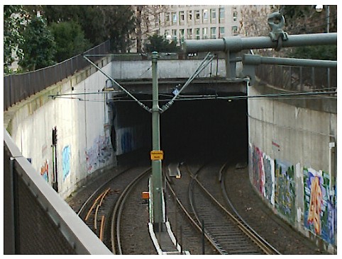
Fig 1: Entrance of one tunnel of Frankfurt Underground It is tune of all tunnels that they are buildings of high value. This is not only due to the high cost of erection but also to the expensive equipment installed inside. To maintain the value a lot of regular maintenance has to be carried out. And for this an-up to-date actual documentation is necessary. Experience has shown that typically the documentation is not up to modern technical standards for maintaining tunnels as economically as possible. Today one still finds conventional documentation in analogous files, lists, card files, or single digital files, along with the well known problems with combining and selecting the information. 2. MAINTENANCE OF TUNNELSTunnels are not just holes in the earth. They are cavities building a three dimensional linear geometry and reaching the surface on each side. They normally contain equipment for traffic. Respecting to the high value of tunnels strategically planned maintenance has to be realized.. In defined intervals inspections have to be carried out. Especially when running nets of tunnels, e.g. at underground networks the maintenance effects high costs. In Germany the maintenance of tunnel buildings is ruled by DIN 1076. It distinguishes between:
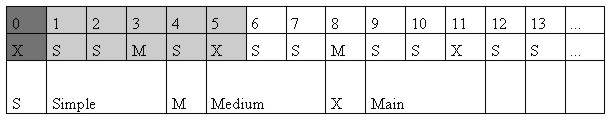
Tab. 1. Times of Inspection As shown in Tab 1 the maintenance starts with a main inspection at the time of the handing over of the building. In the following years simple inspection take place. Every three Years a medium inspection and after six years a main inspection is to be done. The second main inspection takes place when warranty expires, it offers the last chance to find and correct damages.
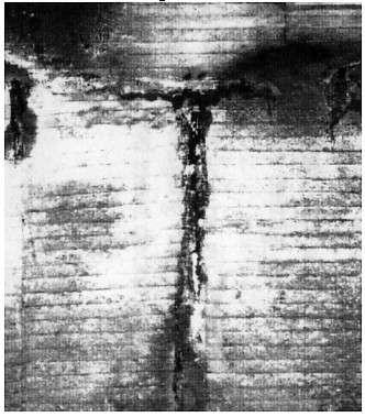
Fig 2: Situation of damage in a tunnel Special inspections will only be made in case of special incidents. After accidents of cars or of trains the tunnel itself and the installed equipment may be damaged. So if need be an inspection is necessary to see to the safety of the building. In case of fire, earth quake or break in of water a special inspection is obligatory. Additionally the maintenance of the installed traffic equipment is to be carried out. This depends on rules for streets or rails, e.g. the DS 853 of the German Rail DB AG. The results of the inspections are a documentation discovered damages. An example is shown in Fig. 2. They are classified in categories such as
The classification is of course a balance between the budget of maintenance and safety. The documentation is normally conventional. This means that plans, analogous files list or digital files are supplemented. This leads to the known problems with combining and selecting the information. Seldom software solutions for documenting inspections are found. In the field of maintenance of tunnels those categories of damages are of interest, which are to be compared with future or past situations. This comparison leads to measures for future repairing. 3. DEMANDS ON A CA-MAINTENANCEThe observation of points of damage has several aspects:
These aspects lead to the demand of an integrated data pool. The comparison of change in situations during the time demands descriptions in which the
are named. These information should be completed by graphical data, which could be pictures or drafts. The integration of the alphanumerical and graphical data leads over to the chances a spatial information system can give. Only these information systems, kinds of GIS, guarantee a conclusion between positions and the information belonging to objects. The documentation of the damages in the appearances, the causes etc. in an integrated data pool opens the chance to produce statistics in an easy and simple way. These statistics give help in planning the maintenance budget for a certain time and improve the procedure of maintenance. So they are to be demanded. An information system for the maintenance has to support the description and the classification for discovered damages. This has to result in the comparison with other damages for a better forecast of estimated consequences. Handling information is always embedded in the processes. Whenever processes are running information on objects are needed for manipulating. Maintenance is a process like many others. So it is to be demanded, that the process of maintenance is projected into the CA-system within the function model. This is valid for all processes depending on data of the tunnel. The embedding is prerequisite for reducing costs by better calculations and for optimising the processes. This nearly global task for a CA-System to maintain tunnels demands that all themes relevant for technical descriptions have to be part of the system. Considering this the maintenance for the building of the tunnel itself and of all its equipment can be supported by the system. This means that all elements are to be described in the data model. For the use of the system it is to be demanded, that all users taking part in running the tunnel have to be connected to the system. So there is a need for a network that connects the users and for an overlay so that the users can identify the specifics of their work So the CA-System for maintenance is an information system for subterranean traffic lines and the targets are:
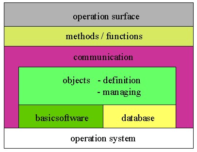
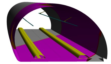
Following this definition and the demands mentioned before an information systems for supporting the maintenance of tunnels was created. 4. SYSTEM STRUCTUREThe prototype of an information system for tunnel maintenance corresponds to the structure displayed in Fig. 3. The core of the system is formed by the objects, or rather their definition and the object administration. Storage is executed within a data bank, which forms the software basis in conjunction with the basic software of the information system. With the aid of communication, which embraces both of them, the exchange of data with external applications and to internal methods and functions can be undertaken. The user gains access to the system via the user surface. The objects within tunnels are geometrically modelled 3-dimensionally for the system and stored in a data model together with the attributive data definition. This definition is accomplished within the scope of a system analysis. The objects concerned are either 3-dimensional bodies, spatial curves or symbols. All objects are or can be linked with alphanumerical data. This allows the user to obtain both selective and combinative scanning of data, thematic presentations as well as freely selectable projections, i.e. isometrics, perspectives and sections. Fig. 4 contains a freely selected section. The record of geometries and alphanumerical data must take place in accordance with the data model. In other words, a geometrical 3-dimensional data acquisition is predetermined. With the help of classical geodetic methods with accompanying extraction of alphanumerical relevant data, this is extremely complicated and both cost and labour intensive. Other methods based on scanner techniques for data acquisition and visualisation were developed. It has to be found out to what extent, the objects presented in a data model and their relevant data can be derived with the help of these methods. With the aid of so-called secondary acquisition methods, i.e. through conversion of analogue into digital components, it is also possible to acquire the data. However, the aim has to be to introduce digital data components, which originate during planning and construction. In the prototype, the objects' geometries were obtained through parameterised design.
Fig 3: Basic setup of system The geometrical accuracy for the expansion and the placing of the objects is also geared to the user's requirements. The following must be taken into consideration in this connection: The expansion of the region of presentation embraces the tunnel and the environments of relevance to tunnel. Under certain circumstances, this field can consist of wide areas of an urban zone, in which magnitudes in the millimetre range are of significance. The geometric accuracy depends on the degree of detail of the individual objects. In this way, a wide range of co-ordinates ensues from overview to detail presentations. In such a case, it is advisable to create special presentations if need be. The presentation of convergences of the tunnel cross-section resulting from geotechnical influences is realised as an example. It is essential that the special graphics are derived from the general data store, i.e. a logical linkage exists, which secures the integrity of the data. The application of a spatial information system for underground transportation facilities especially for the maintenance relates to the fields, which are to be referred to in the following sections. In each case, suitable functionality for targeted application must be catered for. In addition, an information system should be embedded in the user's commercial proceedings. It cannot be accepted given the anticipated investments for the information system that existing operational procedures, the workflows, are not harmonised with the benefits of the system. Conversion results in cost saving and more effective utilisation of the system.
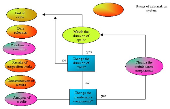
Fig 4: Tunnel cross-section Ensuring that data are kept up-to-date demands organisational embedding in a user's commercial activities. The system's organisational allocation must be undertaken by the department, which operates the tunnel and its facilities. However, it is imperative that those departments, which are responsible for using and updating the data, also have access to them. Principles relating to responsibility and competence have to be adhered to in order to ensure that the data are always up-to-date. Subsequently, the data are updated by the department, which generates them. In other words, in the case of maintenance, all determinants and measures have to be acquired by the responsible department and fed to the information system through a data flow that has to be devised. 5. SYSTEM USAGEWhen having available a full three-dimensional data store, a wide field of applications are possible. The prepared information system documents the tunnel and its facilities. The degree of detail depends on the tasks, which the information system is called on to perform. In this way, it becomes the information source, which can comprehensively supply all the data for the tasks - necessary for all jobs in the tunnel. The results of all jobs must be acquired by the system so that they are available for subsequent works. An information system for the support of the maintenance of tunnels has to fulfil the demands mentioned before. So it is to be embedded into the process of maintenance. An example how this process can be run under the control of the information system is shown in Fig 5. First the functionality has to contain all regulations fixed in the norms, for Germany the DIN 1076. Secondly the system is to be embedded into the processes of the runner of the tunnel. This leads to an automatic observation of the terms in which the different elements of maintenance have to be executed. The system "knowing" in which year which kind of inspection is to be done can be used to extract the single works. This means the works can be planned over the year and the necessary manpower can be calculated.
Fig 5: Course of a maintenance cycle The result of the extraction is a dataset of the to be inspected elements. This can be used to be completed by the results of the inspections, the discovered damages and their classification. At best this is done by using a handheld computer in sight of the objects. The data led back to the system will help to analyse the cause, the effects and the consequences. In the end the maintenance itself can be proved and works, periods and strategy can be adjusted. The comparison of damages in respect of other information will also support the estimation of the causes and the effects. This can lead to a proving of the future strategy in building tunnels. The same applies to changes in the status. Plans for modifications to a tunnel or its facilities require data pertaining to the existing status, in the case of which both geometric and alphanumerical data are of interest, which describe existing objects. The surrounding ground is of interest in conjunction with a tunnel. It is determined by exploratory bores and during the excavation. With these information any changes in the tunnel can be projected. Especially large underground stations have lot of areas. These have to be administrated, because they are of considerable value. They are e.g. used for:
Many areas can be let. It is important to have an overview on the size and the surface of every area for administrating cost and income. The safety from danger like fire is discussed very deeply today. This means the fire protection should also be an aspect of the information system. All data of installed elements dealing with question of fire are to be saved as well as information to fire fighting devices. With these fire protection concept can be proved and continued after all changes in the tunnel. The system may give help also in the case of fire. This means that a possibility has to be created that fire fighters can inform themselves about the actual situation in tunnels. This is important especially for underground nets, which grow over a long time and where different building techniques have been used or multiple uses of areas in underground stations can be found. 6. CONCLUSIONIn sum it is shown, that a spatial information system with its capabilities is able to support many aspects of running a tunnel or a tunnel system. These are the managing of areas in underground stations, the support in documenting and continuing a fire protection concept. as well as documenting the tunnels and the installed equipment for showing the state and for delivering basic plans for the projecting of changing the buildings. Many efforts in running tunnels are spend in the maintenance. Projecting the relevant rules and the necessary workflow as functions into the system will help to optimise the process of maintenance. Optimising normally leads to a reduction of costs. Like every information system the described one facilitates to get knowledge which one can only get on other ways with unacceptable effort. So it helps to preserve the investment by an optimised budget. REFERENCESBill, Ralf „Grundlagen der Geo-Informationssysteme", Band 1 und 2, Wichmann Verlag Karlsruhe 1999 IFGB: Unterirdisches Bauen, Unterlagen für Studium und Praxis, Institut für Grundbau und Bodenmechanik, Technische Universität Braunschweig, 1988 Kehne, Gerd „GIS-Usage for subterranean traffic lines", in „Third Turkish German Joint Geodetic Days" Seite 295-302, ISBN 975-561-159-2, 1999 Spacetec Product information of Spacetec TS 360 , Spacetec GmbH, Salzstraße 47, D-79098 Freiburg. L. Wichter; u.a. Tunnelbau, Expert-Verlag Sindelfingen 1986 BIOGRAPHICAL NOTEGerd Kehne, born in 1958, study of Geodesy in Braunschweig
& Hannover in 1978-1984. 1989 doctorate (Dr.-Ing.) at the
Technical University of Braunschweig with a theses about collecting
data of existing buildings aiming to project an information systems
for buildings. 1989 - 1994 working at private offices on questions of
GIS.. Since 1994 Professor at the Fachhochschule Frankfurt am Main,
University of Applied Sciences for the subjects of Geo-Information. CONTACTProf. Dr.-Ing. Gerd Kehne 15 April 2001 This page is maintained by the FIG Office. Last revised on 15-03-16. |