FIELD PROCEDURES FOR DETERMINING ACHIEVABLE PRECISION OF SURVEYING INSTRUMENTS: LEVELSProf. Jean-Marie BECKER, SwedenKey words: INTRODUCTIONThe surveying profession has been subject to a rapid technical evolution concerning techniques and equipments. Today Surveyors commonly use digital levels, laserplanes, total stations and GPS however ISO (International Standard Organisation) has not yet succeeded to put on the marked standards for these new instruments. ISO still works hardly with updating and harmonisation of earlier standards for older instruments as example EDM, theodolites and levels. Inside ISO, several Technical Commissions (TC59/SC4 and TC172/SC6) have produced standards for levelling instruments. Unfortunately these standards (ISO 8322, ISO 12857,etc) made for the same instrument and for the same purpose namely "Field procedures for determining the accuracy of surveying instruments" are often quite different because of different goals for the TC's. TC59 looked from the building construction views and TC172 from the instrument manufacturer view. Since 1997 a Joint Working-Group for both TC's works on a harmonisation and updating of existing standards. The goal is one standard for one instrument type. THE FIG STANDARDISATION ACTIVITIESInside FIG (International Federation of Surveyors) it is Commission 5 who had the responsibility on questions related to survey instruments and methods. Before 1990 FIG was not much interested in ISO standards. The complexity, diversity and multitude of standards and the special ISO-language made it very difficult for the common FIG member to understand and apply these standards. Often these standards complicated the surveyor life because of the difficulty to be used under "field conditions" and therefore they were neglected. In a first attempt to simplify and clarify the situation about EDM standards, FIG Commission 5 published 1994 at the Melbourne Congress "Recommended procedures for routine checks of Electro-optical distance meters". This document, easy to understand and to apply, was acceptable for the common FIG surveyor, has reach a great success inside the profession and has been translated in several languages. After this success FIG-C5 proposed 1998 at the Congress in Brighton that guidelines for other survey instruments (levels, total stations, GPS, etc) were made until 2002. FIG realised later one, after that EU (European Union) introduced its one CEN (Comité Européen de Normalisation) standards who are not only recommendations but laws regulating professional activities, the increasing importance of it and established 1997 a special Task Force on Standards to co-ordinate the standardisation activities inside FIG and with ISO. FIG is today also hardly involved in the activities of ISO TC 211. Several reports at this FIG C5 workshop will refer to the ISO and FIG activities on the common subjects. After some years of collaboration FIG obtained 1999 the Class A liaison status to ISO/ TC 172 SC6 and TC59. Today several members from FIG-WG 5.1 are directly engaged in the work of ISO/TC 172 SC6 on the establishment of new standards. One of the projects concerns levels and is chaired by J-M Becker. A reviewed draft proposal has been discussed in Berlin March 1999 and sends to the national standard organisations for comment and approval. This standard will probably be finalised and published at the end of this year. The following paper present firstly general and specific surveyor requests on standards, thereafter the recommended field procedures for the determination of the achievable precision with levelling instruments for different applications. Simplified and a full test procedures will be shortly described. For more details we recommend to read the incoming ISO standards. OBJECTIVE OF THE STANDARDSThe objective for the standards is to specify field procedures to be followed each time the achievable precision or "accuracy" for a given surveying instrument used together with its ancillary equipment (tripod, staffs, etc) has to be determined. This will allow the surveyor to investigate that the precision given by the measuring equipment is appropriate to the intended-measuring task. FIG REQUESTS ON STANDARDSThe common requests are as follow:
That is to eliminate confusions, difficulties in applications and in interpretations. Before any fieldwork the surveyor has to answer to the following question: "Can I achieve the required precision ("accuracy") in the project with my equipment, yes or no?" The answer depends from the components of each survey team involved (instruments, ancillary equipment's, personal), execution times, project specificity's, environmental conditions (meteorology, vegetation, groundsurface), etc. It is the complete survey system who is intended to be used who has to be checked.
The question can also be more general concerning several teams, equipment's, projects, times, etc. The Surveyor has to be convinced that if he apply the standards it will help him, otherwise he will not apply them. For these reasons the surveyor require user friendly standards, low time consuming for implementation (about ½ hour) (low-costs) with results easy to be interpreted. FIELD PROCEDURESIn general we follow the approach presented by FIG (1994) for EDM in several steps:
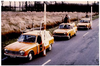
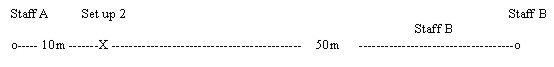
The two described procedures are designed for field and not for laboratory use. The results are specific for each determination and representative only for the particular conditions existing at that time: weather, environment, ground surface, equipment, staff members, etc. The equipment must always be acclimated to the environmental temperature and adjusted before testing in accordance with the manufacturer handbooks. (Step 3). Simplified field testThis test is based on a limited number of measurements (minimum 10) for check of the levelling equipment used especially on construction workside where radial/polar measurements with unequal sight lengths at each set-up are normal. Equal sight lengths are exceptions. Establishment of a test line: In a relatively plane area two points A & B have to be monumented at a distance corresponding to the maximum and minimum sight length ranges that will be used inside each specific project. As example if the needed sight lengths inside a construction project are between 10 and 50m, the distance for AB will be about 60m. Points A and B have to be stable during the test period. The measurements are made in two different steps. The first step with equal site length (30m) as a copy of the accurate test describes before but limited to 10 set-ups. The goal is to determine a reference height difference between A and B, value that is considered as the true value of the height difference of the levelled points A and B.
For the second step the instrument is placed so that the maximum eccentricity for the set-ups is used: in our example: 10m and 50m (See fig below).
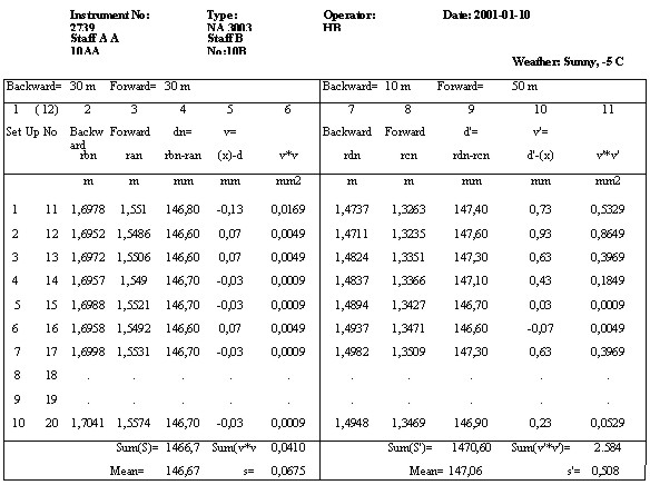
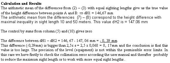
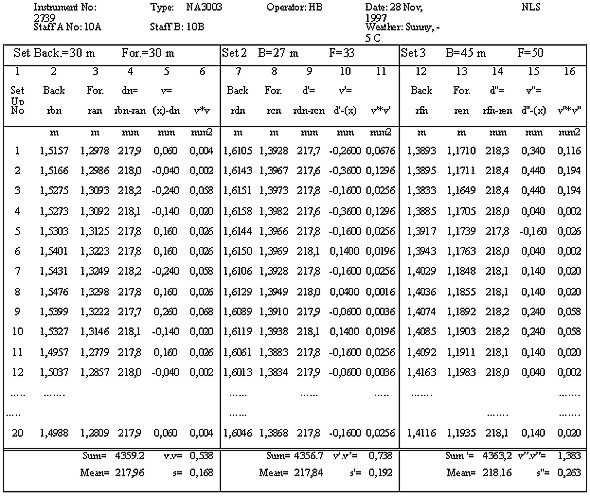
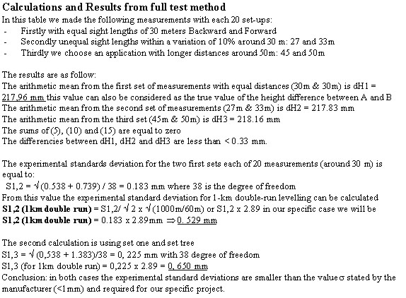
Again all observations on both staffs A and B are made for 10 set-ups: Evaluation of the results Explanations for the calculation and the evaluation of the check are provided in the annexe. The full test procedureThis field method is proposed for the determination of the highest achievable precision using one specific type of equipment. Normally it is for precise levelling (linear applications) where high accuracy is demanded and the set-up observations are made with equal lengths backwards and forwards. The accuracy will be expressed in terms of the standard deviation of 1km double-run levelling. For its implementation we have to establish a test line AB of about 60m in a plane area with homogenous ground surface (gravel preferably) free from vegetation or other disturbing factors (water plane, grass). A and B have to be stable during the whole operations. The chosen site length will be 30m, which is the recommended distance for precise levelling in many countries. Note:
The observations procedure: The measurements are made in two sets with interchanging the positions of the staffs between A and B. Each set consists of n-pairs of readings (preferably 20) backwards to staff A - forward to staff B and vice-versa, resulting in n-height differences. Between each pair of readings a new instrumental set-up has to be made. All details about how to operate, calculate and evaluate are described in the coming standard with one example in appendix. Evaluation of the results: The results analyse is made with statistical tests helping the surveyor to decide if its equipment "yes or no" allow him to achieve the required "accuracy". CONCLUSIONFIG-C5 is grateful that the ISO Technical Committees TC59 and TC172 have taken in account the requests from the surveyor community for the updating and harmonisation of existing standards. We also appreciate the efforts undertaken to prepare standards for the new generation of survey instruments like total stations, laserplanes and perhaps GPS. We hope that these standards will soon be reality. FIG Commission 5 will contribute with its experts (WG 5,1) to the elaboration of this standards through its collaboration with ISO and the participation in the work. Furthermore FIG-C5 will help the surveyors to implement these standards in the best way. BIOGRAPHICAL NOTEJean-Marie Becker, Chairman of FIG Commission 5 Positioning & Measurement, Member of ISO TC59 & ISO/TC172/SC6-JWG, actually at the Department of International questions., National Land Survey of Sweden ANNEX 11 - EXAMPLE FOR SIMPLIFIED TEST METHOD(All observations are in metres, calculations in mm)
ANNEX 22 -Full test method
CONTACTProf. Jean-Marie Becker 22 April 2001 This page is maintained by the FIG Office. Last revised on 15-03-16. |