Article of the Month -
December 2009
|
GNSS CORS - Reference Frames and Services
Volker SCHWIEGER, Germany, Mikael LILJE, Sweden, Rob SARIB,
Australia
 This article in .pdf-format
(21 pages and 690 KB)
This article in .pdf-format
(21 pages and 690 KB)
1) This paper has been prepared and presented at
the 7th FIG Regional Conference in Hanoi, Vietnam, 19-22 October 2009.
Key words: Reference Frames, Geodetic Datums, GNSS, GPS, CORS,
Positioning
SUMMARY
Nowadays the time of GPS or even GNSS static baseline determination
is almost out-of-date for everyday applications. The present trends are
to continuously observe and measure using GNSS, install permanent GNSS
base stations or networks and provide real time accurate positioning. If
you put these three trends together you have an advanced component of
geoscience infrastructure known as a GNSS CORS network. These networks
need to have a geodetic datum, meaning that they have to be linked to
the available terrestrial reference frames. Such GNSS CORS networks are
or will be the primary means by which numerous users can access and
realize position that is based on a geodetic datum. In some regions,
GNSS CORS networks are so well developed and dynamic that they have a
more prominent role than the existing classical passive geodetic
infrastructure in reference frame determination or monitoring.
This paper will focus on the relationship of GNSS CORS with global
and regional reference frames. It will provide procedures for realizing
the link between the GNSS CORS and the available reference frames. An
overview on the key aspects of a GNSS CORS site and CORS network will be
articulated. Some information regarding the concepts of virtual
reference station and of area-correction parameters as well as of the
master-auxiliary-concept will also be discussed. In addition, this paper
will outline the various positioning services that GNSS CORS networks
could provide.
1. MOTIVATION
One of the main trends in modern geosciences is the monitoring of the
planet earth as a whole realized by the Global Earth Observing System
(GEOSS) and, as a part of it, the Global Geodetic Observing System
(GGOS). Apart from other topics its task is to maintain the stability of
and to provide open access to the geometric and gravimetric reference
frames as well as time series of data and products, by ensuring the
generation of uninterrupted state-of-the-art global observation related
to the three fundamental aspects of geodesy, namely geometry and
kinematics, earth orientation and rotation, and the gravity field and
its variability (IAG 2009). These monitoring tasks help to understand
climate change, are usable to predict and monitor natural disasters,
help to realise sustainable development and may lead to a global
structural policy. One important module is the establishing, monitoring
and making available of a global accurate and reliable reference frame.
This is already realised by the International Reference Frame (ITRF)
with its different realisations. This reference frame is non-active but
is a near real time accessible geodetic datum.
On the other side there is a strong world-wide need for positions in
real time regarding positioning, navigation as well as guidance and
control. These positions are needed for mass market applications like
car navigation systems as well as geodetic applications like state
survey, cadastral measurements or engineering surveys. This is a reason
that some GNSS receivers are continuously operated as so called CORS
(Continuously Operating Reference Stations) to allow the real time
availability. Additionally CORS can be united into networks to reduce
errors and to have the capability to deliver positioning services for a
country, a state or even world-wide.
In any case for high accurate applications especially in geoscience
the connection to global terrestrial reference frames like ITRF is very
important. Consequently, the authors of this paper will provide some
basic procedures regarding the linking of CORS networks to reference
frames and also an insight into the various positioning infrastructure
and services that can emanate from such networks.
2. THE FUNDAMENTALS OF REFERENCE FRAMES
From a spatial information perspective, it is common for spatial
datasets and geographical information data to extend over national or
regional boundaries and for the global surveyors or organisations across
continents. In this situation it is needed to have a common reference
frame for the collection, storage, visualisation and exchanging of the
information. ITRF is the most accurate reference frame that exists
internationally. ITRF is defined by the International Earth Rotation and
Reference System Service (IERS). The present trend is that more and more
regions as well as countries are using a solution based on ITRF.
ITRF is continuously monitored by geodetic observations from numerous
scientific and geodetic measuring facilities or networks. The reference
frame can be considered as being well-defined, long term stable, highly
accurate and easily accessible and is the basis for all precise
positioning on and near the Earth’s surface. Coordinates, as well as
velocities, in an International Terrestrial Reference System (ITRS) are
computed at different epochs and the various solutions are given a year
code for identification as ITRF97, ITRF2005 and so on. Due to improved
measurement techniques, more observations and sites, new models and
analysis tools the coordinates changes for a certain point between the
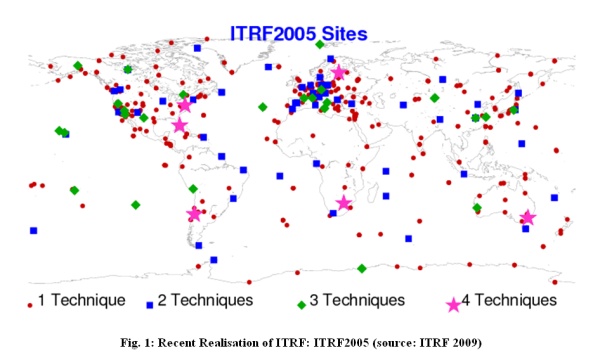
different ITRF. The latest ITRF solution, ITRF 2005, was determined from
a combination of observations the following space-based geodetic
techniques:
- GPS (Global Positioning System) respectively GNSS (Global
Navigation Satellite System),
- VLBI (very long baseline interferometry),
- SLR (satellite laser ranging),
- LLR (lunar laser ranging) and
- DORIS (doppler orbitography and radio positioning integrated by
satellite).
These measurement techniques all have their strengths and weaknesses
but the combination produces a strong terrestrial reference frame. This
reference frame is determined from geodetic observations from globally
distributed networks, however the solution could be improved if there
were more spaced based geodetic observations in the southern hemisphere.
Well defined parameters for a 7-parameter three-dimensional similarity
transformation are used for transformation between the different ITRF
realisations. The velocities valid in the respective reference frame
have to be transformed as well. In literature this procedure is referred
to as 14 parameter transformation. The procedure is described in IERS
(2004) and the transformation parameters are given e.g. in ITRF (2009).
A new solution, ITRF 2008, is expected to be released during 2009.
ITRF coordinates or positions are articulated as three dimensional
geocentric or Earth Centred Cartesian co-ordinates ie “X, Y and Z”. To
convert these Cartesian coordinates to geographic respectively
ellipsoidal coordinates (latitudes and longitudes and ellipsoidal
height) the GRS80 ellipsoid is pre-dominantly used as it is the best
fitting analytical model for the earth’s surface. However in some cases
it is necessary to describe an ITRF position in plane (grid)
co-ordinates (eg two dimensions – eastings and northings) hence a
mathematical map projection is used. A popular map projection which
retains the angle is the Universal Transverse Mercator (UTM) projection.
Today it is common to determine a point’s position using Global
Navigation Satellite Systems (GNSS). Positions are not absolute
quantities. They are dependent on the reference frame to which they are
referred. If GPS is used then the point’s position is determined in the
reference system WGS 84. Observing in a good GNSS environment, the
absolute accuracy for a single point position fix is ± 5 - 10 metres in
the horizontal – ie 2 dimensions at the 2 sigma (2σ) confidence level.
WGS84 or the World Geodetic System 1984 is the geodetic reference
system used by the GNSS - “GPS”. It was developed for the United States
Defence Mapping Agency (DMA), now called NGA (National Geospatial -
Intelligence Agency). Although the name WGS84 has remained the same, it
has been enhanced on several occasions to a point where it is now
aligned on the cm-level to ITRF2000 at epoch 2001.0 and referenced as
WGS 84 (G1150) referred to the GPS week no 1150 (NIMA 2006). The origin
of the WGS84 framework is also the earth’s centre of mass. For other
GNSS we can mention that Galileo will use ITRF as reference system
whereby the others will consider aligning as close as possible to ITRF.
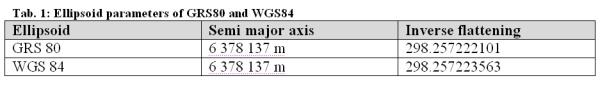
According to ICSM (2009), the ellipsoid recommended by the
International Association of Geodesy (IAG) is the Geodetic Reference
System 1980 ellipsoid. This ellipsoid was used by the United States
Defence Mapping Agency with WGS84. The parameters of the WGS84 ellipsoid
“....are identical to those for the Geodetic Reference System 1980
(GRS80) ellipsoid with one minor exception. The form coefficient J2 used
for the second degree zonal is that of the WGS84 Earth Gravitational
Model rather than the notation J2 used with GRS80.” - DMA (1987). The
end result is that the GRS80 and WGS84 ellipsoids have a very small
difference in the inverse flattening, but this difference is
insignificant for most practical applications.
For all practical purposes, an ITRF based geodetic datum and WGS84
are the same for the epochs defined. The difference is below the
cm-level for each coordinate. As a consequence it is very seldom that
the reference frame for GNSS CORS (Continuously Operating Reference
Station) networks is not based on ITRF.
If mm to cm accuracy is required then GNSS phase data from points of
known position in the region are needed. The resulting coordinates for
the point to be determined will then be in the same reference frame as
the point with given coordinates, the reference point. This local point
could be a permanent GNSS station in continuously operating reference
station (CORS) network that is linked to an International Terrestrial
Reference Frame (ITRF). The same is valid for non-accurate code data
solution on the 1 to 10 m level. Here the difference between WGS84 and
any ITRF solution is without importance.
Regarding the height system by using a GNSS CORS network the surveyor
will normally derive a height based on the reference ellipsoid ie the
GRS80. Most users however are working with physical heights based on a
local height datum (ie local mean sea level) and thus need to relate the
derived ellipsoid height to this local height datum. This is achieved by
using a geoid model for the subject survey area or by determining a
local geoid by interpolation. A more sophisticated approach is given by
Jäger et al. (2003).
3. GNSS CORS
3.1 Definition and General Technical Background
The most known GNSS is the Global Positioning System (GPS) developed
by the United States Department of Defence and is currently managed by
the United States Air Force 50th Space Wing. Competing and complementary
systems are GLONASS and in the future, among others, the European
Galileo and the Chinese Compass. There are also other GNSS in operation
or being developed such as the Japanese “QZSS” and the Indian Regional
Navigational Satellite System “IRNSS”.
For all GNSS measurements of geodetic accuracy you will need at least
two simultaneously measuring receivers and the use of phase
observations. In general, the one on a site with known coordinates is
called the reference station (also known as the ‘master’ or ‘base’). The
one located on the site with unknown coordinates is called the rover.
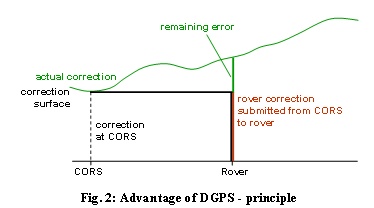
This procedure is used for code observations as well. In this case the
accuracy is somewhat worse around 0.5 m or even between 1 m and 3 m
depending on the measuring technique (compare section 3.2). This
determination of relative coordinates is called the DGPS-principle.
Figure 2 presents the general idea behind it. The error influences that
are the same or nearly the same at both sites are eliminated or at least
strongly reduced. This covers all influences but multipath and
measurement noise.
The development of GNSS, especially of GPS, has lead to the operation
of continuous operating reference stations (CORS) that acquire GPS
signals without any interruption. Additionally these CORS have the task
to store the data and in some circumstances process the data and then
transmit this data to rover receivers. CORS help the users by
economizing one GPS receiver as the operation of the reference station
is performed by the service provider of the CORS network. Thereby
networks using code or phase observation show different characteristics.
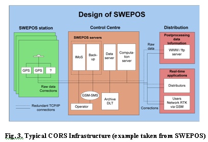
Every CORS network consists of several GNSS stations interconnected
by reliable communications to enable real time computations and control.
Each station, as a minimum, requires a receiver (preferably geodetic
quality), an antenna (affixed to a stable monument), communications and
a power supply. In some cases a computer is installed additionally for
data transmission and control, however modern day receivers, with
suitable communications and network management software) now have the
ability to stream raw data back to a central server location. In ideal
cases a supplementary configuration is used for reliability or back up
reasons (Refer to Figure 3). Additionally a user interface is required
to configure and maintain the network. This may be realized remotely
e.g. by radio communication or by digital communication (mobile phone
network) or via internet connection. If we are talking about an offline
network that provides the information to the user for post-processing,
the stored data files use “receiver independent exchange format”, that
is RINEX .. For online networks real time kinematic (RTK) is the
application and the RTCM (Radio Technical Commission for Maritime
Services) format is normally used for data transmission. The RTCM format
is an internationally accepted standard format for real time data
transmission of differential (RTK) GNSS corrections from GNSS CORS
(including networks) to mobile GNSS receivers. Details of RTCM 3.0 can
be found at: http://www.rtcm.org/overview.php#Standards.
It is also important to note that as CORS networks continue to be
established globally there will be a need to categorise or develop a
hierarchy of CORS networks. Such a concept, espoused by Rizos (2008),
should also be considered when developing CORS networks or positioning
infrastructure. The proposed hierarchy or tier structure by Rizos (2008)
is as follows:
- Tier 1 – ultra-high accuracy CORS networks equipped with
geodetic quality receivers that can track all the broadcast
GNSS/RNSS (regional navigation satellite systems)
frequencies/signals, have a stable antenna monument, comply with the
International GNSS Service (IGS) Site Guidelines, and are
established for ultra-high accuracy networks to support
geo-scientific research and global reference frame definition. Tier
1 contributes to the IGS.
- Tier 2 – are the high accuracy CORS networks equipped
with geodetic quality receivers, that can track all the broadcast
GNSS/RNSS frequencies/signals, have a stable antenna monument, and
comply with the International GNSS Service (IGS) Site Guidelines.
These networks are normally operated by National geodetic agencies
or State governments for the purpose of maintaining national
geodetic datums and providing the fundamental ‘backbone’ of a
national geospatial reference frame.
- Tier 3 – are the CORS networks equipped with “minimum
interoperable configuration design” receivers that can track the
interoperable L1-L5 GNSS/RNSS frequencies / signals. These stations
densify the National CORS networks, and are operated by agencies
such as State governments, or private companies providing commercial
differential GNSS (DGNSS) services. The services are generally for
positioning applications; and real-time access to the datum and
positioning services. The accuracy of these networks is nominally
‘fit for purpose’. The site and monumentation requirements for these
CORS networks may not be as stringent as those for Tier 1or 2,
however reliable and quality communication and power infrastructure
is often necessary due to commercial obligations.
3.2 Classification
CORS networks are established for numerous reasons however the
accuracy of the end product, position, will vary as it is dependent on
how it is dervied. A distinction therefore has to be made between DGPS
(differential GPS) using code observations and PDGPS (precise DGPS)
using carrier phase observations.
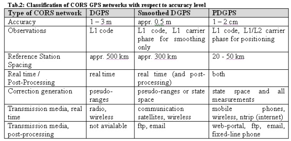
The DGPS networks provide a standard deviation of 1 to 3 m. In this
case pseudo-range differences are used to correct the observations at
the rover side. This princple works well for code observations and
distances up to some 100 kms; so a sparse CORS network is adequate. An
advanced variant is the use of carrier phases to smooth the code
observations at the rover receiver. The standard deviation is better
than 0.5 m. One example for this kind of network is the WADGPS (Wide
Area DGPS) firstly established in the US and published by Kee (1996).
Typical realisations are the American WAAS and the European EGNOS
systems. Mostly the corrections are provided using the state-space
appoach (e.g. Wübbena & Willgalis 2001) delivering modelled biases for
the different error sources. The latter is the same approach that is
used for PDGPS networks. Additionally all the measurement data of the
reference station is transferred to the rover that provides the
solution. Here the ambiguities of the carrier phase observations are
solved and fixed to integer values; for long baselines or
ionospherically disturbed measurements they can only be fixed to real
values. In this case the GNSS-experts speak about float solutions. Using
dense networks the accuracy reaches 1 to 2 cm standard deviation. The
real time variant is called real time kinematic (RTK) although it is not
really a kinematic application. In general the measurements are taken in
static mode, but the technique may be used for kinematic data
acquisition as well. Table 2 follows the abbreviation GPS instead of
GNSS, since still most users unse GPS only, although the wording DGNSS
and PGNSS would be more correct.
Additionally users distinguish between post-processing and real time
networks. The latter requiring a wirelesss connection to transfer the
corrections generated at the references station network by the service
provider. The first one may use email contacts, fixed network or moble
phones for data transfer or even web-portals for data download via
internet.
3.3 PDGPS Network Approach
In general a PDGPS service provider owns or operates a CORS GNSS res.
GPS network that is capable of estimating or resolving the ambiguities
of all CORS as one homogeneous model in post-processing or in real time.
This is often referred to as a network solution within a GNSS CORS
network.
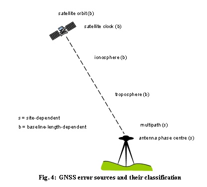
Generally spoken the GNSS error sources may be separated into
satellite-related, receiver-related and propagation media related. This
classification scheme however is not suited for the network approach of
CORS as the error sources need to be divided into site-dependent and
baseline-length-dependent. The first are not influenced by a network
solution. For the latter a network solution improves the result; in
other words the errors decrease explicitly. The error sources depending
on the baseline length are
- satellite orbit and clock error as well as
- tropospheric and ionospheric influences
The most important error source of these is the ionospheric one. The
site-dependent errors like multipath, antenna phase centre variations
and measurement noise are not reduced by the network approach. Figure 4
shows the improvement by a network solution in a simplified way for the
two-dimensional case (two CORS).
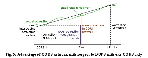
The two main advantages of GNSS CORS networks are the reduction of
baseline dependent errors and the automatic referencing of the GNSS
measurements to the reference frame and datum needed for the results
(see section 4 as well).
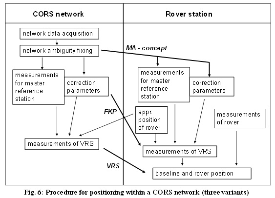
As written before the CORS network is mainly driven to eliminate
baseline length dependent errors. For this we have to deal with the
abbreviations FKP (area correction parameters), VRS (virtual reference
station) and MAC (master – auxiliary concept). The three concepts only
differ by the steps that are realized at the rover respectively within
the CORS network. All these abbreviations, more or less, stand for the
same procedure:
- Acquisition of all measurements within the network,
- Fixing of the ambiguities within the network,
- Determination of area correction parameters (FKP),
- Generation of measurements for one reference station,
- Estimation of the measurements for a virtual reference station
(VRS) by the use of the approximate position of the rover,
- Determination of the baselines and
- Finally the rover positioning using the rover measurements
The abbreviations are chosen due to the information the rover
receives from the CORS network; e.g. the transmission of the virtual
reference station name the method to VRS.
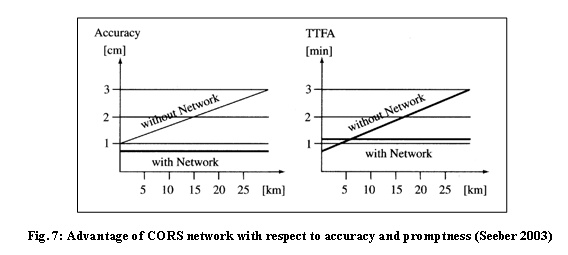
If we focus on PDGPS networks the accuracy as well as the promptness
of the measurement is improved with respect to the respective simple
PDGPS solution. The promptness is given in terms of “time to fix
ambiguity” (TTFA) and the accuracy in terms of standard deviation.
Seeber (2003) outlines that the use of network procedures increases the
accuracy from 3 cm to better than 1 cm in the same time shorten the TTFA
from 3 minutes to around one minute for a 30 km baseline. These
numerical values are valid for mid latitudes. The gain will be even
higher for equatorial or polar regions, where strong ionospheric
gradients occur. But for these geographic locations the network has to
be even denser than in the mid latitudes.
3.4 Post-processing within CORS Network
In general one has to distinguish between CORS networks for
post-processing applications and real time applications. The latter are
more wide-spread in densely populated countries like e.g. Hong Kong
(SatRef) or Germany; the latter country having three competing services
(SAPOS, ASCOS and Trimble Now). For these coutries the real time network
appoach described in 3.3 may be realised in post-processing via email or
web-interface (Refer to Table 2) as well.
Another possibility is to download the observation data of the CORS
(reference station) in RINEX files or special compressed RINEX files and
to process the data using software that is available to the respective
user. This method is preferred, if highest accuracy should be reached.
The RMS of the determined coordinates will be better by a factor of two
to three with respect to the real time solutions. These services cover
code and phase data. The quality of the results depends on the avialable
software and the knowledge regarding GNSS processing. It is worth to
mention that the International GNSS Service (IGS) provides RINEX data
for stations all over the world.
A third possibility especially for users that are non-GNNS experts
are so called online-processing services. Here the user acquires data in
the field, respectively for the stations that he likes to determine. The
acquired raw data is then transformed into RINEX files and up loaded to
the post-processing service. The latter is generally realised through a
web-intreface or via email. The service provider will do the
post-processing of the data together with the data of the reference
stations that are at their disposal. After some minutes the positions
will be provided to the user e.g. via email. Obviously the results of
this service are not under control of the user, but on the other hand
the results will use unique standards for processing and, most
important, non-experienced users will get reliable coordinates only some
hours or even minutes after the measurements have taken place.
4. LINKING OF CORS NETWORKS TO REFERENCE FRAMES
4.1 Importance of Linking Local Datums, GNSS CORS Networks to ITRF
The majority of organisations involved with geo-science activity,
management of geo-spatial datasets or infrastructure generally use a
geodetic datum or at least some form of survey or mapping datum in their
geo-referencing framework. The importance of using a datum or reference
system to underpin their science, datasets or infrastructure allows the
operator to effectively and efficiently collect, integrate, manipulate,
analyse and store their positional data in a standard coordinate format.
Issues can arise however when the subject data needs to be incorporated
and used in another agency’s information system whose datum or reference
system is not the same. The normal solution for this typical problem is
to determine a set of mathematical transformation parameters or block
shifts based on common points and then transform or adjust one dataset
on to another. For small and localised datasets this type of solution
will suffice, however with large and different types of datasets which
could span over an entire local region or state or country or even
continent, integration becomes more problematic and exaggerated,
especially if there are several reference systems or datums involved,
and the reference systems origins have been determined by a mix of space
or classical geodesy. Complex transformation matrices could be
determined and adjustments performed. However for datasets or
infrastructure at a national level this is often a significant exercise.
Typical examples for a complex but very accurate transformation using
previously measured stations in both datum definitions and finite
element method is developed and implemented by Jäger et al. (2003).
As a consequence many countries or organizations use a sophisticated,
and often simple and long term solution which is to migrate their
positional datasets to a global terrestrial reference frame, in general
ITRF. Fortunately many organisations or national survey agencies who are
in the business of managing geo-spatial datasets / infrastructure or
geo-science activity, have access to GNSS CORS infrastructure directly
or through positioning service providers thus linking to ITRF should be
a viable and practical option. For example Germany introduced ETRF89, a
regional densification of the ITRF for Europe, as national reference
system in 1995; at the same time implementing UTM-coordinates as
two-dimensional projection coordinate system (ADV 2005). The long-term
historic German geodetic datum was legally abolished and will disappear
in practice within the following years.
There are also many countries or organizations that need to
rationalize such a change to an ITRF based geodetic datum and / or
require resources to develop infrastructure, such as GNSS CORS networks,
to determine and realise an ITRF based datum or reference frame. To
assist such agencies, to create a business or strategic or justification
plan, the following reasons or drivers for linking to ITRF should be
considered and expanded upon;
- An ITRF based datum allows for a single standard for collecting,
storing and using geographic or survey related data. This will
ensure compatibility across various geographic, land and survey
systems at the local, regional, national and global level.
- ITRF based GNSS CORS networks should form the basis for Spatial
Data or Positioning Infrastructure which are the enabling
infrastructures to manage a country’s fundamental spatial data sets.
That is, it underpins or is the reference layer for the cadastre or
land administration system, transit / road networks, infrastructure
corridors like gas, water, power, communications etc.
- ITRF based positioning solutions provide direct compatibility
with GNSS measurements and mapping or geographic information system
(GIS) which are also normally based on an ITRF based geodetic datum
- An ITRF geodetic framework minimises the need for casual users
to understand datum transformations
- An ITRF geodetic framework allows more efficient use of an
organisations’ spatial data resources by reducing need for
duplication and unnecessary translations
- ITRF datasets helps promote wider use of spatial data through
one user friendly data environment
- ITRF geodetic datums reduces the risk of confusion as GNSS, GIS
and navigation systems become more widely used and integrated into
business and recreational activities.
- ITRF based geospatial infrastructure through the contribution of
relevant geodetic data (such as GNSS CORS observations) facilitates
the resolution of regional or global issues in the scientific or
social arena. For example - provide geodetic data for the
development of a vertical reference frame to assist scientific
research into climate change, sea level rise and tsunami warning
systems; make possible accurate monitoring of plate tectonics and
earth quakes; assist with the implementation of disaster management
strategies; aid with the development of regional terrestrial
reference frames or improvements to the ITRF.
- The adoption of ITRF strategies will transfer and develop or
enhance the related skills, knowledge and experience during the
implementation of the ITRF based geodetic datum thus building the
capacity and setting the foundations for an organization as the
market in the real time positioning services arena continues to
rapidly grow.
4.2 General Procedure for linking GNSS CORS to ITRF
In most developed countries it is common for a national network of
GNSS CORS reference stations to exist and be an integral part of
geo-spatial infrastructure. It is also normal for such a network to be
connected to the International GNSS Service (IGS) network and thus these
base stations will have accurate ITRF coordinates. When establishing a
new stand-alone or a network of CORS, it is recommended to connect the
new station or network to the national CORS network. As a consequence,
the national survey organization should be contacted for relevant
geodetic information on the national network and how to obtain data from
the national CORS sites. In the circumstance when there is no suitable
national CORS network, then the alternative is to connect the new
stand-alone or a network of CORS to the IGS network. For general
information on the IGS network and how to obtain RINEX data files refer
to website http://igscb.jpl.nasa.gov/
To determine the ITRF coordinates of a new stand-alone CORS or a new
network of CORS, the following is recommended :
- For a network select one station in the new network as the
“master” or “reference” or “base”.
- At the master or the new stand-alone CORS log data (30 second or
1 minute rate is sufficient) for at least 24 hours, but ideally for
up to 7 days.
- Download or acquire RINEX data from the closest IGS station or
from the closest national CORS.
- Process the baseline from the IGS station, or from the national
CORS, to the master using 24 hours of data. If data has been logged
for several days, process the baseline for different 24-hour periods
and take the mean.
- If possible, it is highly recommended to process additional
baselines to the master from one or two supplementary IGS or
national CORS. The final position or solution should be the mean of
the results.
- If performed correctly, this basic procedure should provide very
accurate ITRF coordinates for the master or the new stand-alone and
link the subject CORS to the IGS or national CORS network.
It is even better to connect two or even more sites to the IGS
network simultaneously or even not at the same time. If the first is
considered, a network solution using least-square adjustment techniques
is preferred. By doing this the following second step may be eliminated
or may need less effort. But the second step is needed for densification
purpose in any case, since the ITRF coordinates of the stations of the
new network have to be fiducially accurate, i.e. the network has to have
a very high degree of relative accuracy between the stations. The
following procedure for this second step is recommended:
- At all new CORS log data (30 second or 1 minute rate is
sufficient) for at least 24 hours, or preferably for several days.
- Using the ITRF coordinates of the master as the reference point,
process all the baselines of the network using 24 hours of data. If
additional data has been collected then repeat for another one or
two 24-hour periods. Adjust the network if adjustment software is
available.
- If performed correctly, this basic procedure should provide ITRF
coordinates for all new CORS in the network and have a high degree
of relative accuracy.
With respect to the determination of heights for the new CORS network
or stand-alone CORS, the derived height will be based on the reference
ellipsoid ie Geodetic Reference System 1980 (GRS80). Most organisations
or users however are often working with or require their solution in
physical heights based on a local height datum (such as local mean sea
level) that has originated from a combination of levelling and
gravimetric measurements. Consequently an empirical relationship or the
undulation between the derived ellipsoidal heights to this local height
datum needs to be known. This is achieved by determining or using an
existing geoid model for the subject survey area or deriving a height
transformation grid for the survey. You have to take the uncertainties
of the geoid undulations into account, if you want to calculate the
accuracy the transformed physical heights in the local datum.
In situations whereby there are no existing ITRF based networks, and
processing software is unavailable or not suitable, then there are also
internet based online processing services which derive ITRF coordinates
or positions, if sufficient RINEX data has been submitted for
processing. These systems will provide a position solution based on an
ITRF coordinate system by calculating baselines from nearby GNSS CORS
having known ITRF co-ordinates. These reference stations could be
located in another country and / or official IGS sites.
4.3 MONITORING THE RELATIONSHIP BETWEEN GNSS COORS AND ITRF
There are some stations in a national CORS network that are of a
higher order as they are the stations which define the national
geospatial reference system and therefore are the link between the ITRF
and the national refernce frame realisation. The remaining CORS in the
network are normally for datum densification that facilates and supports
important positioning services (such as a networked RTK service = real
time CORS network), and other downstream applications. Essentially, all
existing stations are streaming or collecting 24 hours of data for
science, research or applications which require a certain level of
quality, integrity and reliability thus it is vital that the stability
of such infrastructure is monitored and subsequently modelled.
Furthermore, as a manager of a GNSS CORS network it is crucial to have a
regime in place that monitors and measures the CORS station involved are
stable and that the defintion of the national geospatial reference
system is stable.
The fundamental method of monitering a CORS network is to implement a
system that will compute coordinates for each CORS station at regular
intervals (every day, every week, every month ...) automatically.
Ideally the system should then compare the published ITRF values against
observed, analyse the solutions, provide statistical information of the
results and over time model the change or deformation. In some cases the
resultant positions could be used to refine national geodetic networks
or primary spatial datasets, such as the cadastre.
As an example here we use the Swedish CORS network SWEPOS™. Currently
the network consists of 175 stations. The defining stations in SWEREF
99, the swedish national reference system, are all well monumented
permanent stations on bedrock. There are 21 SWEPOS-stations and
additional stations in Finland, Denmark and Norway that partly also
could be used for the definition of SWEREF 99. All SWEPOS-stations and
some additional stations in neighbouring countries are in¬cluded in the
daily/weekly processing of SWEPOS, which is the basis for the check of
the used coordinates at the permanent stations. Each SWEPOS-station is
deter¬mined in SWEREF 99 by a Helmert-fit to the closest defining
stations and compared to the official used coordinates. Coordinates are
up¬dated when found necessary due to equipment replacement or local
station motions.
5. CORS NETWORKS EXAMPLES and POSITIONING SERVICES
A contemporary CORS network can provide a variety of positioning
services for ultra high accuracy measurements for geodesy to general
navigation applications. Examples of services could be:
- Downloading of code or phase data (such as RINEX files) through
WWW/FTP for post-processing
- Provision of an Automated Processing Service via the internet
- Network RTK Service (phase observations)
- Network DGNSS Service (code observations)
- Transmitting raw data streams to users or other service
providers using NTRIP
The type and level of positioning services that a CORS network could
implement or adopt will largely depend on the interest, possibility,
resources available to the operators as well as the demand of the
market. Some operators may also enter into such services so as to offset
costs associated with maintaining this type of geodetic infrastructure
that is used to perform their core geoscience business. Below you will
find some examples of CORS networks from the Asia Pacific region as well
as from European countries and web links that describe their services.
Information on other CORS networks is available on the FIG Commission 5
webpage.
SWEPOS is a national CORS network covering Sweden and run by the
national mapping authority. The system consists of more than 170
stations where approximately 30 are of higher quality (mounted on
bedrock and so on) and the rest are mounted on buildings. SWEPOS has
several services and is used for positioning on the metre level down to
scientific work on the sub-mm level (Norin et al., 2008). Since April
1st 2006, data for both GPS and GLONASS is provided in the RTCM standard
format, version 3.0. The expected position accuracy is approximately 15
mm horizontally (68 %) and 25 mm vertically (68 %). Many of the users of
SWEPOS Network RTK service do not belong to the conventional surveying
community. This has resulted in the development of a field manual for
network RTK measurements with the service which is distributed to all
new users. The major Swedish GNSS equipment dealers also provide
ready-to-go packages for the SWEPOS positioning services. These packages
are tailor-made for different applications, and minimize the need for
new users to master all aspects of their equipment in order to use the
positioning services. A recent trend is the increasing use of the
network RTK service for machine guidance and precision navigation, most
notably in the form of flexible and redundant services that are
tailor-made for large-scale projects. Download for post-processing is
supported as well.
In Germany three service providers have their own networks and offer
products to the users: SAPOS run by the German state surveys, ASCOS is
privately driven by the companies EADS and Allsat GmbH (together:
AXIO-NET) and Trimble VRS Now of Trimble. All the three providers offer
real time services on code and phase level as well as post-processing
services. For further details the authors refer e.g. to Schenk (2009),
Loef (2009) and Wegener (2009). For the web links is referred to SAPOS
(2009), ASCOS (2009) and Trimble (2009). For German service providers
SAPOS uses GSM and internet as well as the option radio transmission for
communication. Positioning is realized in different accuracy steps from
1 to 2 cm (HEPS service) up to 0.5 m to 3 m (EPS service). The main RTK
network concept is the use of area correction parameters (FKP), but VRS
and MAC can be applied as well, if the respective rovers are in use. For
further information is referred to SAPOS (2009). The Axio-net GmbH
provides its ASCOS services via GSM and internet as well. Here VRS is
the only RTK network concept (ASCOS 2009). The newest provider on the
German market is Trimble pushing its Trimble VRS Now network as
all-in-a-hand solution for surveyors and others. The technical
specifications are more or less similar to the before mentioned service
providers (Trimble 2009). SAPOS and AXIO-NET are offering download for
post-processing applications as well.
Operational CORS networks in the Asia Pacific region are:
- Malaysia Real Time Kinematic GPS network (MyRTKnet) has
been established by The Department of Survey and Mapping Malaysia
(JUPEM) and is a VRS network of permanent CORS.
Website -
http://www.geodesi.jupem.gov.my/MyRTKnet/index.htm
- The Singapore Satellite Positioning Reference Network,
SiReNT is a nation-wide reference network developed to support
real-time high precision land surveying and other positioning
applications. An initiative by Singapore Land Authority (SLA),
SiReNT provides Differential GPS (DGPS) services which supports the
latest technology of Network-RTK.
Website –
http://www.sirent.inlis.gov.sg/
- The Hong Kong Survey and Mapping Office (SMO) of Lands
Department has applied new technology to improve the quality of
services in recent years. It makes use of the Global Positioning
System, GPS technology of United States to develop a local satellite
positioning system, namely "Hong Kong Satellite Positioning
Reference Station Network" (SatRef).
Website -
http://www.geodetic.gov.hk/smo/index.htm
- The National Geodetic Survey (NGS), an office of NOAA's
National Ocean Service, coordinates a network of continuously
operating reference stations (CORS). Each CORS site provides Global
Navigation Satellite System (GNSS - GPS and GLONASS) carrier phase
and code range measurements in support of 3-dimensional positioning
activities throughout the United States and its territories.
Website -
http://www.ngs.noaa.gov/CORS/
- Korea has 44 CORS for active GPS applications and the
central station in the National Geographic Information Institute for
control and management. The central station collects its data
captured from CORS, and processes for the base-line determination
Website -
http://www.ngii.go.kr/jsp/ngii_eng/html/main/project/project_02.html
- The Australian Regional GPS Network (ARGN) consists of a
network of permanent geodetic quality GPS receivers, on geologically
stable marks, in Australia and its Territories, with eight stations
within Australia known as the Australian Fiducial Network (AFN).
These sites provide the geodetic framework for the spatial data
infrastructure in Australia and its territories. They also provide
input for the measurement of earth processes, such as crustal
dynamics and sea level rise. Data from the ARGN network also
contributes to the International GPS Service.
Website -
http://www.ga.gov.au/geodesy/argn/
- The Crustal Movement Observation Network of China, or
CMONOC, is a network of large scale and high precision that covers
over the whole China mainland with GPS as its main observation
technique and combined with existing techniques of Space Geodesy
such as VLBI and SLR, and combined with precise leveling and
gravimetry.
Website -
http://www.igs.org.cn:8080/cmonoc/index_en.jsp
- PositioNZ is Land Information New Zealand's Global
Positioning System Active Control Network. Through this site you can
download GPS 30 second RINEX files from the active control stations
which you can use with remote GPS station data to determine precise
positions in terms of New Zealand Geodetic Datum 2000.
Website -
http://www.linz.govt.nz/geodetic/positionz/index.aspx
- The Japanese Geographical Survey Institute has
established about 1,200 GPS-based control stations throughout the
country. Movement of the land of Japan is daily monitored by GPS
Earth Observation Network System (GEONET). Observation data thus
obtained are made available for actual survey works and for studies
of earthquakes and volcanic activities.
Website -
http://www.gsi.go.jp/ENGLISH/page_e30030.html
Additionally fully automated online post-processing is possible. Here
the authors refer to the following exemplary web locations to find out
more about such online GNSS processing services and their requirements:
REFERENCES
- AdV (2005): Richtlinien für den einheitlichen Raumbezug des
amtlichen Vermessungswesens in der Bundesrepublik Deutschland.
- ASCOS (2009): http://www.ascos.de. Last accessed august 2009.
- Defense Mapping Agency (1987): Department of Defense World
Geodetic System 1984, its definition and relationships with local
geodetic systems, DMA Technical report 8350.2
FIG Fact Sheet, 2007. GNSS CORS Networks Principles. Produced by FIG
Commission 5 – Positioning and Measurement, 2007. Available on line
at
http://www.fig.net/commission5/wg52/manuals.htm
- FIG Fact Sheet, 2007. Reference Frames, Datums and GNSS CORS
Networks. Produced by FIG Commission 5 – Positioning and
Measurement, 2007.Available at
http://www.fig.net/commission5/wg52/manuals.htm
- IAG (2009): Web Page of Global Geodetic Observing System,
http://www.iag-ggos.org/
- International Association of Geodesy (IAG), last edited: 24.
June 2009.
- ICSM (2009): Geocentric Datum of Australia Technical Manual –
Version 2.3 (1),
- Intergovernmental Committee on Surveying and Mapping (ICSM).
July 2009
Available at
http://www.icsm.gov.au/icsm/gda/gdatm/gdav2.3.pdf
- IERS (2004): IERS Conventions 2003, IERS Technical Note No. 32
by D.D. McCarthy and G. Petit, Bundesamt für Kartographie,
Frankfurt, 2004.
- ITRF (2009): Web-page of International Terrestrial Reference
Frame (ITRF).
http://itrf.ensg.ign.fr/ITRF_solutions/, last accessed July
2009.
- Jäger, R., Kälber, S., Schneid, S., Seiler, S. (2003): Precise
Vertical Reference Surface Representation and Precise Transformation
of Classical Networks to ETRS89 / ITRF - General Concepts and
Realisation of Databases for GIS, GNSS and Navigation Applications
in and outside Europe. Proceedings GNSS2003 – The European
Navigation Conference, Graz, April 22-25, 2003.
Kee, C (1996): Wide Area Differential GPS. In: Parkinson, Spilker
(editors, 1996): Global Positioning System – Theory and
Applications, Vol. 2, Chapter 3.
- Leica Geosystems, 2005. GPS Reference Stations and Networks – An
Introductory Guide. Heerbrugg, Switzerland.
- Loef, P. (2009): ascos – one-stop-shop for precise satellite
positioning services. In: GNSS 2009: Systeme, Dienste, Anwendungen.
Beiträge zum 83. DVW-Seminar, 18.-19.03.2009, Dresden, Germany.
- Rizos, C. (2008) Multi-Constellation GNSS/ RNSS from the
Perspective of High Accuracy Users in Australia, Journal of Spatial
Sciences, Vol. 53, No.2, December, pp 29-63.
Available at
http://www.gmat.unsw.edu.au/snap/publications/rizos_2008a.pdf
- SAPOS (2009): http://www.sapos.de. Last accessed august 2009.
Schenk, A. (2009): SAPOS – Der amtliche
Satellitenpositonierungsdienst. In: GNSS 2009: Systeme, Dienste,
Anwendungen. Beiträge zum 83. DVW-Seminar, 18.-19.03.2009, Dresden,
Germany.
- Seeber, G. (2003): Satellite Geodesy. 2nd Edition. Walter de
Gruyter, Berlin.
NIMA (2006): Abbendum to NIMA TR 8350.2, Implementation of the World
geodetic System (WGS84) Reference Frame G1150,
http://earth-info.nga.mil/GandG/publications/tr8350.2/tr8350_2.html,
last accessed July 2009.
- Norin, D., Jonsson, B, Wiklund, P. (2008): SWEPOS and its
GNSS-based positioning services. Presented at the FIG Working Week,
Stockholm, Sweden, 2008.
- Trimble (2009):
http://global.trimble.com/de/. Last accessed August 2009.
- Wegener, V. (2009): Trimble VRS Now – RTK einfach nutzen. In:
GNSS 2009: Systeme, Dienste, Anwendungen. Beiträge zum 83.
DVW-Seminar, 18.-19.03.2009, Dresden, Germany.
Wübbena, G., Willgalis, S. (2001): State Space Approach for Precise
Real Time Positioning in GPS Reference Networks. Internat. Symp. on
Kinematic Systems in Geodesy, Geomatics and Navigation (KIS2001),
Banff, Kanada.
BIOGRAPHICAL NOTES
Volker Schwieger obtained his Diplom-Engineer „Geodesy“from
the University of Hannover in 1989. In 1998 he gets his Doctor Engineer
at the University of Hannover as well and in 2004 he made his
Habilitation at University Stuttgart. Since 2001 he has been a member of
the research team at the Institute for Applications of Geodesy to
Engineering at University Stuttgart, where he heads the metrology
department since 2003. His research activities cover among others
engineering geodesy, kinematic positioning, machine guidance and, of
course, GNSS. He is also Vice Chair of FIG Commission 5 and head of FIG
Working Group 5.4 “GNSS”.
Robert Sarib, Manager, Survey Services in the Land Information
Division of the Northern Territory Government’s Department of Planning
and Infrastructure, Licensed Surveyor, member of the newly formed
Surveying and Spatial Sciences Institute, and Vice Chair of
Administration for FIG Commission 5 – Position and Measurement.
Robert Sarib obtained his degree in Bachelor Applied Science – Survey
and Mapping from Curtin University of Technology Western Australia in
1989. He was registered to practice as a Licensed Surveyor in the
Northern Territory, Australia in 1991 and achieved this during his
employment with the Northern Territory Government. Since then he has
work in the private sector as a cadastral surveyor, and more recently
re-employed by the Northern Territory Government to manage the Northern
Territory Geospatial Reference System and administer the Survey Services
work unit of the Office of the Surveyor General. He also holds a
Graduate Certificate in Public Sector Management received from the
Flinders University of South Australia.
Mr Sarib is currently a member of the FIG Commission 5.2 Working
Group – Reference Frame in Practice, and the Northern Territory delegate
on the Australian Inter-governmental Committee on Survey and Mapping -
Geodesy Technical Sub Committee. He is the Northern Territory
representative on the interim board of the Surveying and Spatial
Sciences Institute. He is also a board member of the Surveyors Board of
Northern Territory for Licensed or Registered surveyors.
Mr. Mikael Lilje graduated with a M.Sc. with emphasis on
geodesy and photogrammetry from the Royal Institute of Technology
(Stockholm, Sweden) in 1993. He has been working at Lantmäteriet (the
Swedish mapping, cadastral and land registration authority) since 1994,
mainly at the Geodetic Research Division. Since 2001, he is the head of
the group Reference frames and coordinate systems. He is also incoming
chair of FIG Commission 5 as well as chair of the FIG Working Group on
“Reference Frames in Practice”.
CONTACTS
Dr.-Ing. habil. Volker Schwieger
University Stuttgart
Institute for Application of Geodesy to Engineering
Geschwister-Scholl-Str. 24 D
D-70174 Stuttgart
GERMANY
Tel. +49 711 685 84064
Fax +49 711 685 84044
Email:
volker.schwieger@iagb.uni-stuttgart.de
Web site:
http://www.uni-stuttgart.de/iagb/
Mr Robert Sarib
Department of Planning and Infrastructure
GPO Box 1680
Darwin NT
AUSTRALIA
Tel. +61 8 8995 5360
Fax. +61 8 8995 5365
Email: robert.sarib@nt.gov.au
Web site: www.dpi.nt.gov.au
Mr Mikael Lilje
Geodetic Research Division
Lantmäteriet
SE-801 82 Gävle
SWEDEN
Tel. +46 26 63 37 42
Fax. +46 26 61 06 76
Email: mikael.lilje@lm.se
Web site:
www.lantmateriet.se/geodesi
 |