Article of the Month -
January 2014
|
Innovative and Cost Effective Spatial Positioning
Volker SCHWIEGER, Germany and Mikael LILJE, Sweden
1) This paper was presented
at FIG Working week, 6-10 May 2013 in Abuja, Nigeria. This paper focuses
on surveying of land and the base infrastructure needed for surveying
task. It shows how geodetic marks may be replaced by new infrastructures
like active control networks. Apart from the technical basics, it
outlines the economic benefits with respect to costs and surveying
instruments available to local surveyors.
Key words: GNSS, Cost Effective, Low Cost technology,
Positioning, CORS
SUMMARY
Access to land, improving land use and mapping are
all dependent on that land is mapped and surveyed. This presentation
will focus on surveying of land and the base infrastructure needed for
the surveying task. The authors will show how geodetic marks may be
replaced by new infrastructures like active control networks (e.g. GNSS
CORS networks). Apart from the technical basics of these networks, the
economic benefit of a CORS network will be outlined with respect to
costs and surveying instruments available to local surveyors.
Another focus is on the cost-effective use of
surveying instruments and the use of cost-effective instruments (e.g.
low-cost GNSS). The authors will present a decision table on the base of
accuracy, availability and costs to decide for instruments and
procedures for different tasks as 1D, 2D or 3D surveying. Consequently
the use of technology is dependent on the purpose of the survey as well
as the technique available. Not always is the low-cost or the most
modern technology the most appropriate. The authors talk about the
cost-effective positioning technology and give different examples, e.g.
low-cost GNSS receivers for data acquisition, RTK-GNSS for cadastral
issues or highly precise total stations for engineering survey tasks.
A modern alternative of positional sensors delivering
point measurements are sensors delivering spatial measurements like
terrestrial laser scanners, camera systems and ground-based radar. Here,
the object will be acquired completely and not only chosen points. The
disadvantages may count the high investment costs and the required
specialized knowledge about the evaluation and data analysis. The main
advantage is the availability of a huge amount of data that may serve
different purposes in the future e.g. facility management or new
planning procedures.
Another idea for cost-effective positioning is
kinematic data acquisition. In this case the spatial measurements are
taken from moving platforms like vehicles. Besides the positioning of
the moving sensors, the area measurements are used to create models for
facades, streets or even complete cities. The presentation will give an
introduction to kinematic data acquisition, the so-called mobile
mapping, and compare it in a technical and financial point of view to
normal surveying work. The final outcome of the report will give hints
to decide for an appropriate spatial positioning technique for a given
task or application. The method may be classical point measurements,
static or kinematic area measurements; in any case positional
infrastructure is needed for any positioning tasks.
1. INTRODUCTION
The costs of e.g. personnel and hardware in surveying is always
discussed, no matter if it is done in a developing country or in a
developed country. There is always a need to minimize the costs and
maximize the outcome but still meeting the projects’ requirements. As a
part of this, there is a need to use a technology that is as efficient
as possible to accomplish the task. For a mapping authority it is
important to not only see each project separately but to make sure that
the national geodetic infrastructure is as cost-effective as possible
also for a longer period of time. This means building up a geodetic
infrastructure that is harmonized with the surrounding countries as well
as accessible for the local users. Different techniques vary in
investment costs as well as in maintenance and use. However, the
cheapest technique is not necessarily the most efficient and therefore
not the most cost-effective one. Different types of projects and
environments also demand different techniques.
This paper will shortly discuss different surveying techniques in
terms of cost, need of infrastructure and more. The paper will not give
a clear answer for all types of use and instruments, but hopefully help
a decision maker to understand the possibilities of the surveying
professionals.
It is also important to understand that several of the modern
surveying techniques as DGNSS and RTK all need a certain level of
infrastructure. Not only in terms of accessibility to the reference
frame but also in terms of e.g. mobile phone coverage, power, and roads
and so on.
2. SURVEYING AND POSITIONING INSTRUMENTS
The aim of surveying and of all other positioning
tasks is the determination of point coordinates. Historically it can be
distinguished between 1-dimensional meaning height networks,
2-dimensional meaning horizontal networks as well as true 3-dimensional
networks. State survey has separated height and horizontal networks
since global 3D measurements were not possible and since the height
information is not purely geometrically defined. The 3D networks were
mainly used for local applications only. In the last 25 years GNSS leads
to the possibility of 3D global coordinates, only gravity information
has to be added to get the correct height information (e.g. Seeber,
2003).
In general, the surveying instruments are used to
measure the coordinates indirectly. Examples are the total station
(tachymeter), the level instrument and the GNSS receiver. The first one
measures distances as well as horizontal and vertical angles resulting
in 2- or 3-dimensional coordinates. The standard deviation of the
determined coordinates varies from some cm to sub-mm depending on the
instrument chosen and the measured distance. A total station may be
automated; in this case it is called robotic. The level instruments can
only be used to determine heights by delivering the height differences.
The accuracy level is between 5mm/km double levelling up to 0.3 mm/km
double levelling again depending on the instrument and equipment chosen.
The distance between points should not exceed 100 m for low level
accuracy and 30 m for highest accuracy level. GNSS receivers deliver
3D-coordinates based on distance measurements to 4 satellites minimum.
For survey grade receivers phase information of minimum two receivers
are used simultaneously, thus in general leading to a superior accuracy
compared with navigation grade receivers (see following section). The
coordinate standard deviations show values from some cm to mm depending
on the processing technique and the real time requirement. The technique
supporting this accuracy level is called Precise Differential GNSS
(PDGNSS). Real time solutions as well as post-processing strategies are
supported by positional infrastructure described in section 4. The
precise differential real time solution is in general called Real Time
Kinematic (RTK). (Deumlich & Staiger, 2002) Figure 1 presents a total
station, a digital level and a survey grade receiver, all of them
showing the highest accuracy class. Figure 2 shows the same for low
accuracy instruments. Since the authors will discuss cost-effectiveness
in this article, some figures regarding costs are given in the
following. Please note that these are approximate informative figures
with no connection to the above illustrated instruments. Correct values
have to be determined in a detailed market survey. The costs for total
stations range from 8 000 € for a low level construction grade up to a
30 000 € for a highly accurate robotic total station. Level instruments
vary from 2 000 € to 10 000 € including the equipment (like rods). GNSS
receiver price interval begins at about 8 000 € for a 1-frequency survey
grade receiver up to 20 000 € for a 2-frequency RTK receiver.
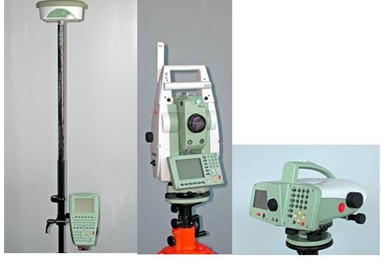
Figure 1: Highly accurate survey instruments: GNSS receiver, total
station, level instrument (from left to right), (source: IIGS)
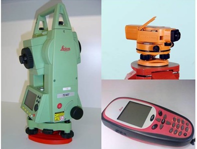
Figure 2: Less accurate survey instruments: total station (left),
level instrument (top right), GNSS receiver (downright), (source: IIGS)
3. LOW-COST INSTRUMENTS
First the authors have to address the question of the
definition of low-cost. In the sense of this article it is meant that
the cost will be at least lower by a factor of ten with respect to the
survey grade instruments of any kind described in the previous section.
The authors will not describe traditional surveying methods like
distance measuring by taping, since these techniques cannot be automated
and will therefore in no case be cost-effective in the future. Regarding
current new technologies, the only instruments to be described in the
low-cost sector are navigation grade GNSS receivers. Total stations and
level instruments have no low-cost equivalent. At the end of the section
the authors will also briefly deal with the idea of positioning using
mobile phones or even smart phones that are an interesting alternative
for some applications.
3.1 GNSS Receivers
As stated in section 2, geodetic GNSS surveys are
based on high-quality GNSS receivers and antennas. Frequently, the
surveying community uses dual-frequency receivers to solve the
ambiguities faster and more reliably. In the last few years,
single-frequency survey receivers have proved to work very reliably
provided that baseline lengths are below 10 km to 15 km. This opens up
the market for receivers that are used for navigation, since these
receivers generally have a single frequency. In general, navigation type
receivers do not use the phase data. This problem is overcome by some
manufactures, which provide access to the code and phase measurements
from the raw via a serial or a USB interface. Some of the manufacturers
(e.g. u-blox) are officially documenting their format. Many navigation
type receivers integrate low-priced, simple antennas directly into their
receiver box, while other receivers are simply connected to an external
antenna via a cable. In the latter case, the antenna may be fixed on the
roof of a car using a magnet on the antenna casing. Portable antennas
usually range in price but start at several €s. In general however, an
antenna and a receiver are sold as a package (Weston & Schwieger, 2010).
The performance quality of navigation type receivers
can be improved by using precise geodetic antennas. In this case the
cost-effectiveness is clearly reduced. Figure 3 presents the combination
of a u-blox low-cost receiver with a charge controller, a battery, a
W-LAN router as well as the antenna together with a choke-ring produced
at the Institute of Engineering Geodesy at the University of Stuttgart
(IIGS). The position standard deviation may reach more or less the same
values like survey grade one-frequency receivers, meaning the mm level
(Zhang & Schwieger, 2013). Currently the influence of the choke-ring is
investigated at the IIGS. The costs for a complete system including the
above equipment is around 2 000 €. A choke ring increases the costs
significantly.
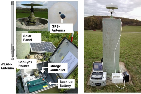
Figure 3: Low-Cost GNSS System (left, Zhang et al., 2012) and Antenna
with Choke Ring (right, Zhang & Schwieger, 2013)
3.2 Mobile Phones and Smart Phones
Other low-cost instruments that may be used for
positioning are mobile phones or smartphones which are able to determine
the position through the mobile phone network or simply by using a
built-in GNSS chip. For GSM network positioning standard deviations
between 30 metres up to some kilometres occur, depending on the
methodology (see e.g. Schwieger 2007). Relying on the built-in GPS chip
delivers standard deviations of some meters with possible outliers up to
the hundred meter level. For all these tasks the problems of centring
the instrument and the coincidence of mechanical centre and electronic
antenna centre need to be solved and restrict the accuracy respectively.
Using so-called assisted GNSS (A-GNSS) for the differential case one may
reach a more reliable accuracy numbers at the same level. If phase data
would be included, standard deviations on the low-cost level could be
reached provided that the mentioned centring and centre problems can be
solved. Up to now this has not been implemented by the mobile phone
providers, but it would be possible to do so (Wirola, 2008). The costs
for mobile phones or even smartphones can be estimated to zero, since is
already the standard for any person working in the field.
4. POSITIONAL INFRASTRUCTURE
4.1 Reference Frames
From a spatial information perspective, it is common
for spatial datasets and geographical information data to extend over
national or regional boundaries and for the global surveyors or
organisations across continents. In this situation it is necessary to
have a common reference frame for the collection, storage, visualisation
and exchanging of information. The harmonization, not only nationally or
regionally but globally, is very important. ITRF is the most accurate
reference frame that existing worldwide. ITRF is defined by the
International Earth Rotation and Reference System Service (IERS). The
present trend is that more and more regions as well as countries are
using a solution based on ITRF. Reference Systems (ITRS) are computed at
different epochs and the solutions are called ITRF.
WGS84 or the World Geodetic System 1984 is the
geodetic reference system used by GPS. It was developed for the United
States Defence Mapping Agency (DMA), now called NGA (National Geospatial
- Intelligence Agency). Although the name WGS84 has remained the same,
it has been enhanced on several occasions to a point where it is now
aligned on the cm-level to ITRF2000 at epoch 2001.0 (Schwieger et al.,
2009).
The International Committee on GNSS (ICG) was formed
as a result of recommendations of the UN Committee on the Peaceful Use
of Outer Space (COPUOS), ratified by the General Assembly of the UN. The
permanent secretariat for ICG is situated at the United Nations Office
for Outer Space Affairs. As part of the role of ICG, the web portal of
ICG (http://www.oosa.unvienna.org/oosa/en/SAP/gnss/icg.html) reports on
the current situation regarding the development of the various GNSS as
well as their alignment to ITRS. It is very clear that interoperability
between the GNSS is important. A GNSS receiver in the future will be
able to use the signals sent from the different GNSS.
4.2 Continuous Operating Reference Station (CORS)
A Continuous Operating Reference Station (CORS) is a
permanently installed geodetic quality receiver and antenna that is
positioned over a monument or point which collects GNSS data 24 hours a
day, every day of the year. Today it is very common that an organization
establishes a number of stations in a network. More or less every
country has at least a network covering the major cities. Several
countries also have networks covering the entire nation. The majority of
the developed countries do have it, but also a major number of
developing countries have so, too. The CORS network is used to define
the reference frame in the specific country and this reference frame
should be aligned with the international ITRF.
A surveyor working with GNSS receivers can use the
information from a CORS to position points. A CORS can also be used for
long-term studies geodynamic effects as well as climate change. A modern
form of using a CORS network enables positioning accuracies that
approach one centimetre or better, even in real time relative to a
worldwide network, such as the ITRF, or to a local network.
For all practical purposes, the ITRF based geodetic
datum and WGS84 are the same for the epochs defined. The difference is
below the cm-level for each coordinate. As a consequence it is very rare
that the reference frame for GNSS CORS (Continuously Operating Reference
Station) networks is not based on ITRF.
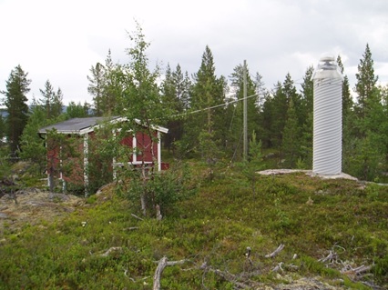
Figure 4: Example of a CORS station (SWEPOS, Sweden)
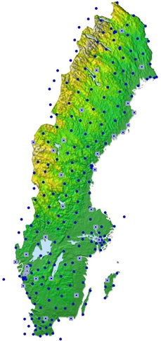
Figure 5: SWEPOS CORS network design
4.3 Mobile Phone Network
For GNSS real time positioning (RTK) as well as for
direct positioning using mobile phones (compare sections 2 and 3), this
network has to be available and accessible. Although it is not regarded
as positional infrastructure at a first glance, it has to be accepted as
positional, too. Figure 6 shows the typical structure of a GSM network
including different colours for different cells that are the base in any
case for some of the positional information available within the
network.
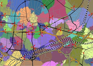
Figure 6: Exemplary mobile phone network with cells and antenna
locations and orientations (source: IIGS)
4.4 Access to Positional Infrastructure
As stated above it is important to get access to
positional infrastructure, since a global or national unified datum is
only possible through this infrastructure, e.g. cadastral measurements
with legal involvement are only valid if they are referred to the
national datum. Additionally, there are positioning techniques needing
the infrastructure as an essential part for the positional task, like
the GNSS RTK measurements or the positioning through the mobile phone
network. This means that the access to positional infrastructure is
important for the surveyors, but also for any other user that needs to
position. There are two levels of access: the post-processing level
(access to Reference Frame, e.g. total station or normal PDGNSS) and the
real time level (access to networks, e.g. RTK and mobile phone
positioning). The access may be not possible due to lack of
infrastructure or due to high access costs for the users, like fees for
the information itself as well as for the communication. It is important
that the infrastructure is built up nationwide and worldwide and that
the access is possible with no or very low costs, so that positioning
can be realized homogeneously and cost-effective (compare section 6).
The cost for a user mainly consists of the fees of the network provider
and possibly the costs for communication (e.g. based on a mobile phone
contract).
5. NEW DEVELOPMENTS
5.1 Spatial Data Acquisition
In the last ten years the point-wise data acquisition
has been complemented by area-wise or better spatial measurements. The
most important is Terrestrial Laser Scanning (TLS) showing a strong
practical importance for cultural heritage applications, documentation
of industrial complexes or railway environment as well as typical
engineering tasks like tunnel convergence measurements and the
documentation of road damages. Laser scanners measure two angles and the
distance to non-marked points. The data rate can be more than a million
points per second and the spatial resolution may reach the mm level for
distances below 100 m. The range of instruments depends on the
measurement principle: the phase comparison scanners are restricted to
around 160 m. In contrast, impulse scanners reach a maximum distance of
4 km. But these values really depend on the products. Nowadays, the
standard deviation for individual points is between one mm and one cm.
Phase comparison scanners show the best values. Figure 7 shows three
recent terrestrial scanners. The main advantage of the laser scanners
are their spatial features. This means that lines, surfaces and bodies
are acquired without the need for a person of touching the object to be
surveyed. With other words, the whole object can be acquired,
documented, analysed and visualized. On the other hand it is more
difficult to measure marked points (e.g. only by spheres). This means,
the scanners cannot, or can only be used with severe difficulties, for
point positioning for surveying or geodetic tasks like cadastral surveys
(e.g. Staiger, 2003). The investment costs vary from 30 000 € to 100 000
€ including equipment and software.
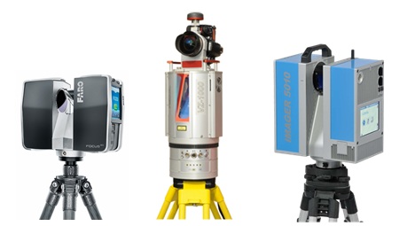
Figure 7: Laser Scanners (Sources: Faro, Riegl, Zöller & Fröhlich)
Other spatial acquisition methods are terrestrial
photogrammetry and the new technology ground-based radar. In principle,
the well-established photogrammetric method delivers the same spatial
data as TLS (point clouds) with a slightly lower accuracy in most
configurations. Ground-based radar is still within the development phase
and needs special arrangements to get spatial data. Currently, it is
well suited for detection of movements in one direction with a very high
accuracy in the mm level (Rödelsperger. 2011).
For all these techniques the access to reference
frames is important, as long as the acquired object shall be integrated
into global or national maps or plans, which is the case for most of the
surveying tasks. Besides, the time to acquire complete objects is much
shorter with respect to point-wise measurements. The draw-backs are the
enormous data volume (360°scan with highest resolution: 10 GB acquired
in 1h 20 m) and the high time exposure for processing, analysis, and
modelling of the acquired data. In general one assumes that processing
takes longer than data acquisition by a factor of three to five.
5.2 Spatial Kinematic Data Acquisition
Spatial data acquisition is the first step to speed
up the acquisition in the field. The next step is to move the sensor or
the multi-sensor system (e.g. Schwieger, 2012) during acquisition.
Additionally, the acquisition is continuous and needs synchronisation of
the different sensors. The general term for this kind of measurement
system is mobile mapping systems. In general, these systems are mounted
on a car or a van consisting of several laser scanners, cameras, and
video cameras for spatial data acquisition. Access to the reference
frame is guaranteed by GNSS - inertial measurement unit combination and
by acquisition of reference points with known coordinates. Besides, the
carrier of the acquisition system can be a satellite, an aircraft, an
unmanned aerial vehicle (UAV) or a railway carriage. Additionally a new
development shows that a laser scanner can be carried on foot by a
single person. The most interesting current development are the UAVs
mainly carrying a camera and some positioning sensors like GNSS or IMU,
as the payload is restricted to some kilograms. In general, the standard
deviations and the spatial and temporal resolution correspond to the
static spatial acquisition methods. Naturally, the results depend on the
integrated sensors and the integration method of the different sensor
information like loosely or tightly coupled Kalman Filter. The time
exposure during data acquisition is further decreasing, whereas the
processing exposure is increasing with respect to time and complexity.
It has to be stated that these tasks can only be fulfilled by
specialized companies one has to contact. A standard surveyor cannot
built up this complex sensor integration nor realize the complex data
evaluation.
6. COST-EFFECTIVE POSITIONING AND DATA ACQUISITION
In this section the authors have to discuss the term
of cost-effective at first. This term should be defined in the way of
fulfilling the requirements with lowest available costs. These
requirements may be the accuracy, e.g. given as standard deviation, or
other quality measures. Also the time may be specified by a given
deadline. In this case, costs or even accuracy may be less important.
Other requirements may be a compulsory special procedure or acquisition
method, e.g. point-wise GNSS determination or spatial object
determination by TLS. It is very important to mention that the
investment costs are only one part of the budget. Highly important are
the personnel costs that vary definitely among different countries, e.g.
developed and developing countries. So, cost-effectiveness may look
quite different for different countries. Furthermore, the
cost-effectiveness may even change in dependence of the salaries and
therefore the personnel costs, when a developing country transforms into
an emerging economy and finally into a developed country. Consequently,
the following table can only give rough ideas for decisions with regard
to instruments and surveying methods to fulfil the requirements
cost-effectively.
This chapter highlights the economic benefits
associated with the reduction of working or investment costs by
implementing the above mentioned techniques. In the following
approximated values and intervals are introduced for personnel. The
authors use an interval from 1 € per hour (lowest level, developing
countries) to 70 € per hour (developed countries) to get a rough
estimation. The costs per year are roughly computed by 20 working days a
month and 8 working hours a day. For the investment costs the authors
assume that the instruments are used for five years, meaning that the
investment costs are divided by five to get the annual costs. For
example a geodetic dual-frequency receiver having a price of 20 000 €
results in 4 000 € operational costs per year.
The simplest decisions can be taken in case an
accuracy requirement is given and the different instruments need the
same personnel for operation. In this case the investment costs are the
only relevant costs. A good example would be the use of a non-motorized
total station for staking out. In this case it makes sense to use the
instrument with the lowest costs in case that it reaches the required
accuracy. For example a total station showing an angle measurement
standard deviation of 0.3 mgon and a distance measurement standard
deviation of 1 mm is superior to one with the respective values like 3
mgon and 5 mm. However, if one has to reach e.g. a 2 cm point standard
deviation, the total station with the lower accuracy is sufficient and
by the way more cost-efficient. This will become more complex if the
superior total station is robotic and only one person is needed to carry
out the survey. In the non-robotic case one would need two persons to
conduct the survey. Here, personnel costs are coming up. The decision
whether the investment for a robotic station is cost-effective depends
on these costs. The same is valid for GNSS measurements. First the
authors only have to look at the price of GNSS receivers (2 frequency
survey grade, 1 frequency survey grade, low-cost). In a second step,
using CORS or CORS networks will economize the costs for one receiver
and the personnel costs for one worker. This has to be compared to the
costs for the communication and the CORS network fees. The estimation
which variant is more cost-effective is realized afterwards.
|
Instrument |
Max. Accuracy |
Investment |
Invest per year |
|
Type A |
1 cm |
8 000 € |
1 600 € |
|
Type B |
0.5 cm |
15 000 € |
3 000 € |
|
Type C |
1 mm |
25 000 € |
5 000 € |
Table 1: Decision matrix based on investment costs only
Table 1 shows a very simple decision matrix in which
one can enter with the standard deviation required and look for the
instrument delivering such accuracy. For example for a requirement of 2
cm a type A instrument is sufficient and consequently the most
cost-effective way to perform the measurements in case that the office
has enough work for this accuracy level. If most of the tasks need 0.5
cm or even more the purchase of a type A instrument is not reasonable.
This matrix is formally valid for different kind of instruments like
total stations and GNSS receivers or even level instruments. To fill
this table with concrete data is not useful since the figures will vary
at least on an annual base; everybody can do this task based on data
that is available to him. The same is valid for the numerical values of
the standard deviations; these are depending on the instruments
available and purchasable.
The second case is applicable to methods where
personal competes to investment costs, e.g. motorized total station
economizes one person or additional fees compete with investment or/and
personnel costs e.g. RTK with or without CORS. Table 2 shows a possible
decision matrix including the most important cost factors. The assumed
investment costs for this table are 25 000 € for a total station, 30 000
€ for a robotic station, 20 000 € for a survey grade GNSS and 2 000 €
for a low-cost GNSS system. The authors point out that the numbers and
prices in the table should not guide your decision, since all cost
factors may look quite different in your country and for your company.
Obviously any personnel reduction shows a very high effect on the
overall costs in the developed countries indicated with (70 €), however
investment has a low influence. Regarding developing countries
investment costs are of greater importance and may influence the overall
costs significantly.
|
Instrument |
Max. Accuracy |
Invest per year |
Personnel per year / (1
€) |
Personnel per year /
(70 €) |
Fees / Commu-nication
per year |
Overall costs
(1 €) |
Overall costs
(70 €) |
|
Total Station |
1 mm |
5 000 € |
4 000 € |
270 000 € |
- |
9 000 € |
275 000 € |
|
Robotic Total Station |
1 mm |
6 000 € |
2 000 € |
135 000 € |
- |
8 000 € |
141 000 € |
|
GNSS
(2 receivers) |
2 mm |
8 000 € |
4 000 € |
270 000 € |
- |
12 000 € |
278 000 € |
|
GNSS / CORS (1
receiver) |
2 mm |
4 000 € |
2 000 € |
135 000 € |
1 000 € |
7 000 € |
140 000 € |
|
Low-Cost GNSS |
5 mm |
1 000 € |
4 000 € |
270 000 € |
- |
5 000 € |
271 000 € |
|
Low-Cost GNSS / CORS
|
5 mm |
500 € |
2 000 € |
135 000 € |
1 000 € |
3 500 € |
138 000 € |
Table 2: Decision matrix taking into account
personnel and investment costs
The last comparison of cost-effectiveness is valid
for huge data amounts. Here, a comparison among point-wise techniques,
static and kinematic spatial data acquisition is realized. One has to
take into account that kinematic acquisition can only be realized by
experts who have to be paid for the job. This means that investment
costs, personnel costs as well as assignment costs need to be compared
to each other. For this case the comparison has to take the time into
account, since e.g. TLS or Mobile Mapping are fast data acquisition
techniques in the field, but require a lot of work in post-processing.
In general, one assumes a factor of five between data acquisition and
post-processing for TLS. Also these figures are very subjective. Table 3
gives a rough estimation for a street of 500 m length including the
acquisition of the facades. All costs are determined for the time
needed. For fieldwork the different sensors show the following
performance: robotic total station 8 days, TLS 2 day, Mobile Mapping 1
hour. In the office the post processing may be: robotic total station 1
day, TLS 5 days, Mobile Mapping 5 days. The investment costs base on the
following figures: robotic station 30 000 € and TLS 100 000 €. The
investment costs are calculated for the time period during which data
acquisition is carried through (8 or 2 days). This presumes that the
instrument is really in use all day and all year. The authors know that
this assumption is optimistic and has to be adapted according to the
company.
|
Method |
Max. Accuracy |
Invest |
Personnel (1 €):
field / office |
Personnel (70 €):
field / office |
Assign-
ment costs |
Overall costs
(1 €) |
Overall costs
(70 €) |
|
Robotic Total Station |
1 mm |
1 000 € |
64 €/ 8 |
€ 4480 € /
560 € |
- |
1 072 € |
6 040 € |
|
TLS |
2 mm |
830 € |
16 € / 40 € |
1120 € /
2 800 € |
- |
886 € |
4 750 € |
|
Mobile Mapping |
2 mm |
- |
- |
- |
10 000 € |
|
10 000 € |
Table 3: Decision matrix for huge data amounts
(example: street of 500 m length including facades)
The surprising result of this table is the fact that
a TLS is more effective than a total station if huge amounts of data are
acquired and the instrument is in use every day. This result is achieved
despite the much higher investment costs. This is valid for developed as
well as for developing countries. Using the assumed costs introduced in
this table, Mobile Mapping would be the most expensive method, but it
would be the fastest, since an expert is realising everything in a short
time period. Please keep in mind that all the cost figures are
subjective, especially the mobile mapping figures are not based on real
experience.
7. SUMMERY AND OUTLOOK
This contribution presented the well-known
positioning techniques and showed some new technical developments
especially with respect to area-wise and spatial data acquisition.
Different accuracy levels and application fields were presented, too. On
the other hand the importance of reference frames and positional
infrastructure could be highlighted. Additionally, it could be shown
that these infrastructures may even help to be more cost-effective.
Finally, a first approach was presented regarding decision tables based
on accuracy as requirement and overall cost as output. Other
requirements as time or reliability could be chosen and need another
decision base. The exact personnel and investment costs need to be known
for a decision. This work has to be carried out by each individual
surveyor in a company or in an office. The development of general,
detailed and more sophisticated tables is the future work to be focused
on.
REFERENCES
Deumlich, F., Staiger, R. (2002): Instrumentenkunde
der Vermessungstechnik. Wichmann Verlag, Heidelberg.
Rödelsperger, C. (2011): Real-time Processing of Ground Based Synthetic
Aperture Radar (GB-SAR) Measurements. Deutsche Geodätische Kommission,
Reihe C, No 668, München, Germany.
Schwieger, V. (2012): Challenges of Kinematic Measurements. FIG Working
Week, Rome, Italy, 06.-10.05.2012.
Schwieger, V. (2007): Positioning within the GSM Network. Proceedings on
6th FIG Regional Conference, San Jose, Costa Rica, 12.-15.11.2007.
Schwieger, V., Lilje, M., Sarib, R. (2009): GNSS CORS – Reference Frames
and Services. 7th FIG Regional Conference, Hanoi, Vietnam,
19.-22.10.2009.
Seeber, G. (2003): Satellite Geodesy. Walter de Gruyter, Berlin.
Staiger, R. (2003): Terrestrial Laser Scanning: Technology, Systems and
Applications. 2nd FIG Regional Conference, Marrakech, Morocco, December
2-5, 2003.
Weston, N.D., Schwieger, V. (2010): Cost Effective GNSS Positioning
Techniques. FIG Publication No 49, FIG Commission 5 Publication. The
International Federation of Surveyors, Copenhagen, Denmark, 2010.
Wirola, L. (2008): High-accuracy Positioning for the Mass Market. FIG
Working Week 2008, Stockholm, Sweden, 14.-19.2008.
Zhang, L., Stange, M., Schwieger, V. (2012): Automatic Low-cost GPS
Monitoring System using WLAN Communication. FIG Working Week, Rome,
Italy, 06.-10.05.2012.
Zhang, L., Schwieger, V. (2013): Investigation regarding Different
Antennas Combined with Low-cost Receiver, FIG Working Week, Abuja,
Nigeria, 06.-10.05.2013.
BIOGRAPHICAL NOTES
Prof. Volker Schwieger
1983 – 1989 Studies of Geodesy in Hannover
1989 Dipl.-Ing. Geodesy (University of Hannover)
1998 Dr.-Ing. Geodesy (University of Hannover)
2004 Habilitation (University of Stuttgart)
2010 Professor and Head of Institute of Engineering Geodesy, University
of Stuttgart
Mr. Mikael Lilje
Mr. Lilje is the Head of the Geodetic Research Department at
Lantmäteriet (the Swedish mapping, cadastral and land registration
authority). He graduated with a M.Sc. with emphasis on geodesy and
photogrammetry from the Royal Institute of Technology (Stockholm,
Sweden) in 1993. He has been working at Lantmäteriet since 1994, mainly
at the Geodetic Research Department. He is the chair of FIG Commission 5
during the period 2011 and 2014 as well as member of the Presidium of
the Nordic Commission on Geodesy and the national member to the
Euro-SDR.
CONTACTS
Prof. Dr.-Ing. habil. Volker Schwieger
University of Stuttgart
Institute of Engineering Geodesy
Geschwister-Scholl-Str. 24 D
D-70174 Stuttgart
GERMANY
Tel. + 49/711-685-84040
Fax + 49/711-685-84044
Email:
volker.schwieger@ingeo.uni-stuttgart.de
Web site:
http://www.uni-stuttgart.de/ingeo/
 |